background image

1

2

7

6

3

5

8

9

12

10

13

13

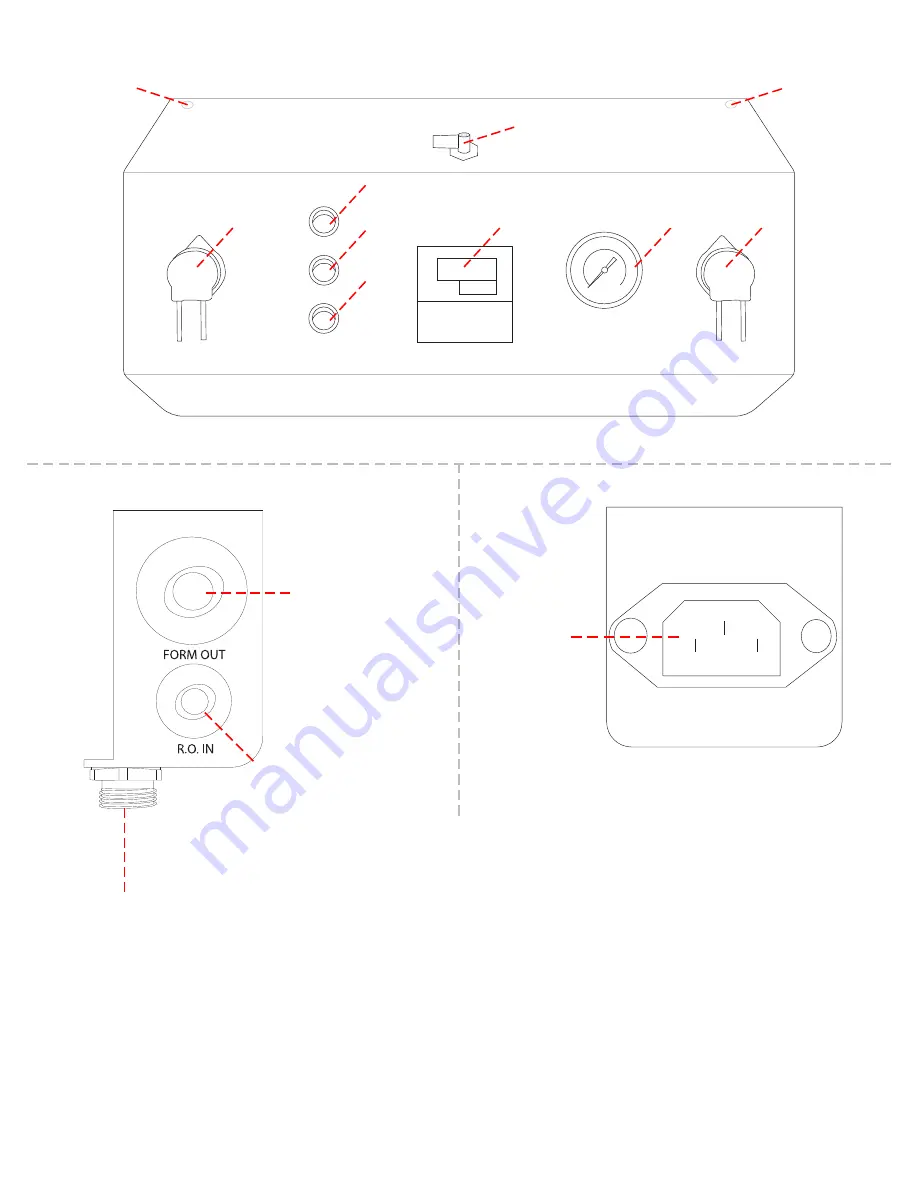
FORMULATION SYSTEM DIAGRAM

4

1 - Formulation Unit Bypass

2 - Peristaltic Pump - A Formula

3 - Delivery Pump Switch

4 - Formulation Switch

5 - Processing Unit Switch

6 - TDS Controller

7 - System Pressure Gauge

8 - Peristaltic Pump - B Formula

9 - Formulation Out Fitting

10 - RO In Fitting

11 - Unit Connection Plug

12 - Power Supply Plug

13 - Panel Screws

11

PAGE 4

Summary of Contents for NEX Formulation Tank

Page 1: ...info gcwater com 20 Opportunity Road Camdenton MO 65020 805 484 1589 www GCWater com NEX Formulation Tank User Guide...

Page 2: ...ission from GC Water Contents 2 Unit Information 3 Formulation System Diagram 4 Installation Hardware 5 Installation Notes 6 POU Connection Layouts 7 Installation Instructions 8 Start Up Instructions...

Page 3: ...20 or 40 Gallons Output Pressure 50 PSI Sound Emission 50dB max Unit Dimensions Height with wheels 20 gallon 26 5 40 Gallon 29 Width 20 gallon 21 40 Gallon 24 Depth 20 gallon 19 5 40 Gallon 26 Ship W...

Page 4: ...2 Peristaltic Pump A Formula 3 Delivery Pump Switch 4 Formulation Switch 5 Processing Unit Switch 6 TDS Controller 7 System Pressure Gauge 8 Peristaltic Pump B Formula 9 Formulation Out Fitting 10 RO...

Page 5: ...s 3 3 8 Equal Tees 1 1 2 x 3 8 Elbow 1 Hand Held TDS Meter 1 1 2 Trunk x 1 2 Branch Tee 1 3 8 Tube x 1 4 FPT Tank Valve 1 1 2 Equal Tee 1 1 2 Tube x 3 8 Stem Enlarger 30 of 1 2 Tubing 6 of Power Cord...

Page 6: ...all be no less than 1 inch 6 Installation must comply with existing local plumbing codes Air gaps must comply with drawings or an approved air gap device may be used In addition some local plumbing co...

Page 7: ...This drawing is theoretical and may not apply to actual situations It is intended to help installers visualize typical plumbing line runs from the water equipment to the store Coffee Tea Brewers Espr...

Page 8: ...ge 16 into the fitting by fully inserting the tubing about 1 2 into the fitting 10 To connect the pressure tank to the formulation tank reference the diagram below The pressure tank does not need to b...

Page 9: ...System switch 7 in Formulation System Diagram on page 44 The water processing unit should turn on and the outgoing pressure gauge should start to read pressure It should read within 10 psi of the inc...

Page 10: ...1 until the monitor displays current water temperature and current TDS level in tank 9 Close the cover to the small black box to protect the buttons from harm NOTE TDS controller must be calibrated ev...

Page 11: ...red in water or a solution Changing the Batteries 1 When the meter displays a flashing battery symbol your batteries are getting weak and should be replaced soon To change the batteries 2 Pull out the...

Page 12: ...ion System Diagram on page 4 3 Turn the yellow handle located on the water processing unit towards ON Location will be in the unit guide that came with the water processing unit Note Tank will not ref...

Page 13: ...lation System Diagram on page 4 are shut off 3 To remove the tubing from the jugs fitting push the collet 1 down flush with the fitting 4 While the collet is depressed pull the tubing 2 out of the fit...

Page 14: ...rvice provider when bypass handle is moved into bypass Only emergency situations require putting the bypass handle into the bypass position Listen for any changes in the sounds coming from the unit Ch...

Page 15: ...o machine or brew coffee during troubleshooting procedures equipment damage may result Y STEP INSTRUCTIONS 1 Check the system pressure gauge reading If the pressure reading is normal 35 60 psi then th...

Page 16: ...t is coming out of the filters on the water processing unit This gauge should be relatively close to the incoming pressure gauge It will typically sit about 5 psi less then the incoming pressure gauge...

Page 17: ...installed and used in compliance with the instructions enclosed with the system The Warranty does not cover any non GC Water parts the costs of repairs or adjustments to the unit that may be needed b...

Reviews: