Page 6 of 28
M434/500 Prototype Commissioning Manual
PN W453101Rev- Nov-02-1998
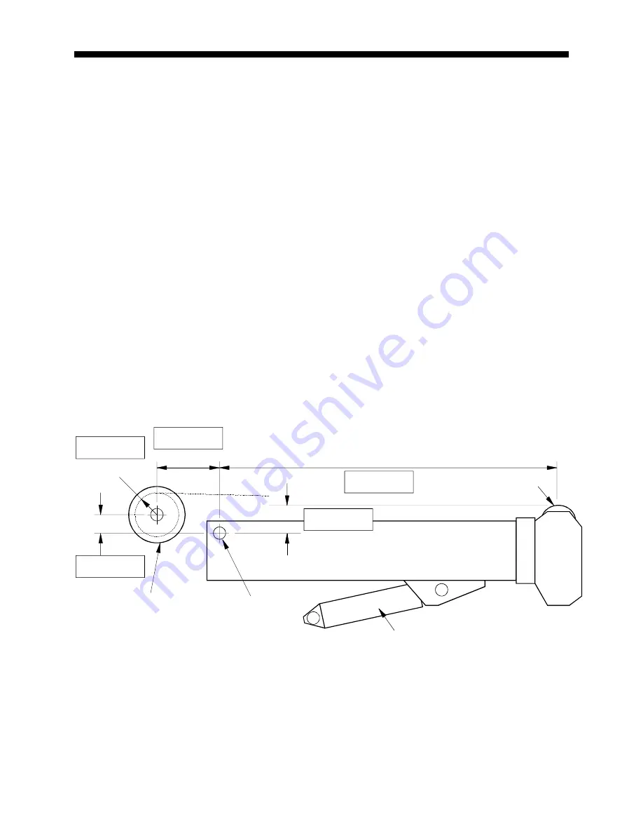
Rear Winch Geometry
Measure each dimension shown using a tape. It is at best, a difficult exercise to measure these
dimensions, but still a necessary check. It is recommended that two people carry out this task and that
care is taken to ensure that clear references are used to measure from.
The boom must be fully retracted and is recommended to be level during these measurements.
The machine carrier is assumed to be level for the purposes of measuring dimensions “G” and “H”.
Dimension “L1”
is the distance parallel to the boom center line between the center of the Boom pivot
and the point at which the hoist rope makes contact with the top sheave at the head of the main boom.
Dimension “J1”
is the distance at 90 degrees to the boom center line between the center of the Boom
pivot and the point at which the hoist rope makes contact with the top sheave at the head of the main
boom.
Dimension “G1”
is the horizontal distance between the center of the Boom Pivot and the center of
rotation of the winch.
Dimension “H1”
is the vertical distance between the center of the Boom pivot and the center of rotation
of the winch.
H1 is negative when the center of the Boom pivot is above the center of rotation of the winch and positive
when it is below
.
Dimension “r1”
is the radius of the winch drum and should include two layers of rope.
Enter the measured values into each of the gray boxes provided below.
*
If the center of the boom pivot is above the center of rotation of the winch, dimension “H1” is negative.
Clearly indicate “+” or “-“.
The above illustration shows dimension “H1” as positive.
H1*
J1
G1
Boom Hoist Cylinder
Boom
Boom Pivot
L1
r1
Top Sheave
Winch 1 (Rear)


