background image


7


Shenyang Guangcheng Technology Co., Ltd.  


Industrial-grade WiFi-CAN converter-GCAN-211 

Product data sheet


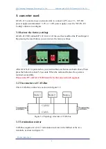
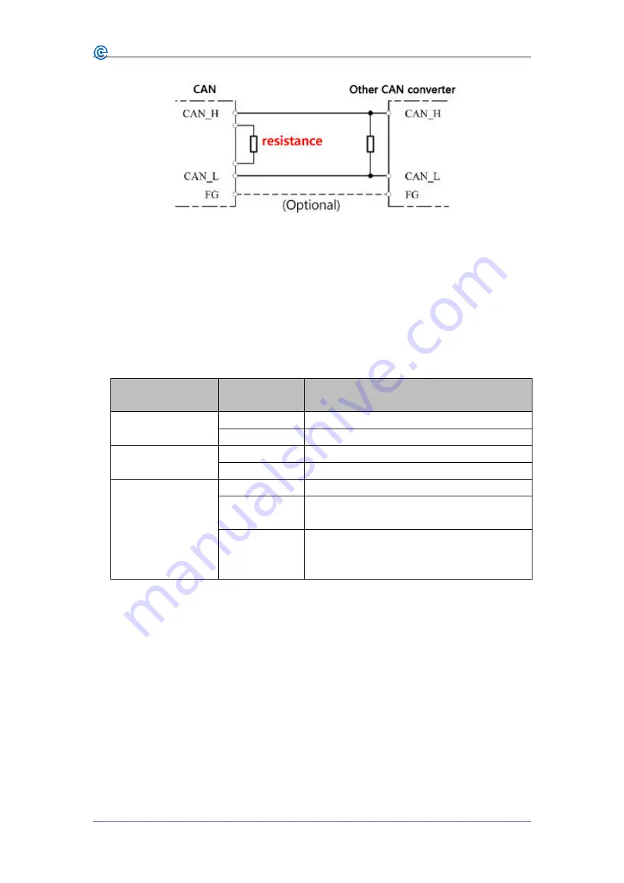
Figure 3.3 GCAN-204 connection to other CAN converter 

Please note: you should connect the two ends of the resistor to CAN_L and 
CAN_H respectively.


3.4 Indicator light 

GCAN-211 converter has one PWR indicator, one SYS indicator, one LAN indicator, 
two CAN indicator, to indicate the converter status. More functions are shown in table 
3.2. 

Indicator light 

Status 

Indicates the status 

PWR 

Bright 

Power supply is normal 

OFF 

Power supply failure 

SYS 

OFF 

Converter initialization failed 

Blinking 

Converter initialization pass, standby state 

CAN1

CAN2 

Red 

CAN-Bus communication failure 

Green 

blinking 

CAN-Bus has data transmission 

Blinking with   

SYS light 

alternately 

The converter enters the reset state 

Table 3.2 Status of the GCAN-202 indicator 


Summary of Contents for 211

Page 1: ...GCAN 211 WiFi CAN converter User Manual Document version V3 01 2017 03 05 ...

Page 2: ...5 3 converter used 6 3 1 Restore the factory settings 6 3 2 The structure of CAN Bus 6 3 3 Termination resistor 6 3 4 Indicator light 7 4 Configuration instructions 8 4 1 Connect the software 8 4 2 Basic information 8 4 3 Finish the configuration 10 4 4 Save load the configuration file 11 4 5 Upgrade GCAN 202 use this function under guidance 11 5 WiFi connection 12 5 1 AP mode 12 5 2 Client statio...

Page 3: ...ature range from 40 to 85 C CAN Bus supports CAN2 0A and CAN2 0B frame format conform to ISO DIS 11898 standards CAN baud rates range from 5Kbps to 1Mbps CAN Bus interface with electrical isolation CAN Bus isolation module insulation voltage DC 1500V Standard Ethernet interface RJ45 supports 10 100M adaptive The working port the target IP and the target port can be modified Support agreement ETHER...

Page 4: ...ial grade WiFi CAN converter GCAN 211 Product data sheet 2 Installation 2 1 Dimension drawings The shell size of the GCAN 202 is shown in Figure 2 1 Figure 2 1 Dimension drawings 2 2 Connect to PC Users can use WiFi to connect directly to the device ...

Page 5: ...logy Co Ltd Industrial grade WiFi CAN converter GCAN 211 Product data sheet 2 3 Connect to CAN Bus In practical use most of the time just connected the CAN_H to CAN_H and CAN_L connected to CAN_L then communication can be realized ...

Page 6: ... the IP and forget it By pressing the reset button you can restore the factory settings After GCAN 211 is powered on you can find the reset button as shown above Then press the button for about 5 6 seconds When the indicator flashes the system is restored successfully Please note PC and GCAN 202 must be in the same network segment 3 2 The structure of CAN Bus This is CAN Bus connection as shown in...

Page 7: ...S indicator one LAN indicator two CAN indicator to indicate the converter status More functions are shown in table 3 2 Indicator light Status Indicates the status PWR Bright Power supply is normal OFF Power supply failure SYS OFF Converter initialization failed Blinking Converter initialization pass standby state CAN1 CAN2 Red CAN Bus communication failure Green blinking CAN Bus has data transmiss...

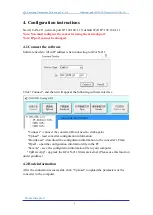
Page 8: ...11 Click Connect and then it will appear the following software interface Connect connect the converter Do not need to click again Upload read converter configuration information DownLoad download the configuration information to the converter s Flash Open open the configuration information file in the PC SaveAs save the configuration information file to your computer UpDate App upgrade the GCAN 2...

Page 9: ... IP Address Info WiFi side parameter setting CAN1 CAN2 Info CAN bus parameter setting 4 2 1 WiFi parameter settings Click IP Address Info to enter the WiFi parameter setting interface IP Address Info set the WiFi IP address GateWay set up a WiFi gateway Subnet Mask set the WiFi subnet mask DNS set up DNS ...

Page 10: ... and 20 bytes of data Note When the communication to determine the wireless network card IP and device IP in the same network segment 4 2 2 CAN Bus parameter setting Click CAN1 CAN2 Info to enter the CAN Bus parameter setting interface TCP Port set the CAN Bus communication port CAN Baud sets the CAN Bus communication baud rate CAN Mode set the CAN Bus operating mode CAN Filter not open the defaul...

Page 11: ...e note power on again after the completion of the download and then the new configuration will take effect 4 4 Save load the configuration file You can click SaveAs save the data in the computer This configuration file can also be opened by the button Open for later use 4 5 Upgrade GCAN 202 use this function under guidance If you need to upgrade please contact us ...

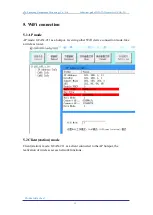
Page 12: ...oduct data sheet 5 WiFi connection 5 1 AP mode AP mode GCAN 211 as a hotspot receiving other WiFi device connection mode like a wireless router 5 2 Client station mode Client station mode GCAN 211 as a client connected to the AP hotspot the realization of wireless access network functions ...

Page 13: ...13 Shenyang Guangcheng Technology Co Ltd Industrial grade WiFi CAN converter GCAN 211 Product data sheet ...

Page 14: ...standard CAN2 0A B CAN baud rate 5Kbit s 1Mbit s Electrical isolation 1500V DC DC CAN termination resistor Has been integrated through the DIP switch to select whether to enable Power supply Power supply voltage 9 30V DC Power supply current 50mA 24V DC Environmental testing Power supply voltage 40 85 Power supply current 15 90 RH no condensation EMC test EN 55024 2011 09 EN 55022 2011 12 Protecti...

Page 15: ...Guangcheng Technology Co Ltd Address Industrial Design Center No 42 Chongshan Middle Road Huanggu District Shenyang City Liaoning Province QQ 2881884588 E mail 2881884588 qq com Tel 86 024 31230060 Website www gcgd net Sales and service Tel 86 18309815706 After sales service telephone Number 86 13840170070 WeChat Number 13840170070 ...

Reviews: