GC-1502 user manual
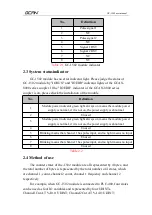
No.
Definition
1
Pulse signal 1
2
NC
3
Pulse signal 2
4
NC
5
Signal 1 RST
6
Signal 2 RST
7
NC
8
NC
Table 2.1
GC-1502 module indicator
2.3 System statusindicator
GC-1502 module has no error indicator light. Please judge the status of
GC-1502 module by "IORUN" and "IOERR" indicator lights of the GCAN-
8000 series coupler. If the "IO ERR" indicator of the GCAN-8000 series
coupler is on, please check the installation of the module.
No.
Definition
1
Module power indicator green light always on means the module power
supply is normal, if it is not on, the power supply is abnormal
2
Unused
3
Module power indicator green light always on means the module power
supply is normal, if it is not on, the power supply is abnormal
4
Unused
5
Blinking means that channel 1 has pulse input, and no light means no input
6
Unused
7
Blinking means that channel 1 has pulse input, and no light means no input
8
Unused
Table 2.2
2.4 Method of use
The counter states of the -1502 module are all represented by 4 bytes, and
the total number of bytes is represented by the total number of 4 states, which
are channel 1, count, channel 2 count, channel 1 frequency and channel 2
respectively
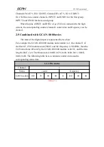
For example, when GC-1502 module is connected to PLC-400, four states
can be used as four IO variables and represented by four UDINTs.
Channel1Cnt AT % I0.0: UDINT; Channel2Cnt AT % I4.0: UDINT;


