GC-1502 user manual
2. Installation
This chapter will describe the installation method, wiring method,
meaning of the indicator and meaning of the interface of the GC-1502 module.
2.1 Module fixing
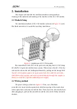
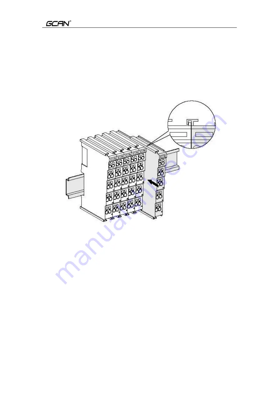
The installation method of GC-1502 module as shown in
Figure 2.1
and a
flat-blade screwdriver is needed for auxiliary installation.
Figure 2.1
Installation of GC-1502 module
First install the GCAN-PLC on the guide rail and plug the GC-1502 along
GCAN-PLC's right side until the lock is stuck. When remove the GC-1502, the
user need to release the self-locking mechanism by pulling out the orange label.
The GC-1502 module needs to be used with GCAN-PLC-400/510 or GCAN-
8000/8100 series couplers, and can be powered directly through the coupler, so
there is no need for a separate additional power supply.
2.2 Wiring method
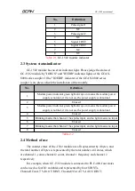
The power wiring as shown in
figure 2.2
. First, use a flat-blade
screwdriver to insert into the square hole, hold the top edge of the metal sheet
in the square hole, and press toward the hole. Then, insert the wire into the hole.
After plugging in, pull out the screwdriver and the wire can be firmly locked in
the hole.


