Vhandy technology
GCAN-2008 user manual
Terminal
No.
Definition
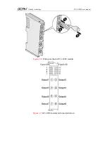
output1
1
Digital output 1
output2
2
Digital output 2
output3
3
Digital output 3
output4
4
Digital output 4
output5
5
Digital output 5
output6
6
Digital output 6
output7
7
Digital output 7
output8
8
Digital output 8
Table 2.1
GC-2008 module indicator
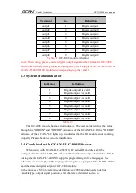
Note: When using, please connect digital output signal to the terminal of GC-2008
and connect the reference ground to the negative power supply of GCAN-PLC-400 or
GCAN-IO-8000/8100 modules (corresponding to pins 5 and 6).
2.3 System statusindicator
Indicators
Definition
1
Digital output1 is valid.
2
Digital output 2 is valid.
3
Digital output 3 is valid.
4
Digital output 4 is valid.
5
Digital output 5 is valid.
6
Digital output 6 is valid.
7
Digital output 7 is valid.
8
Digital output 8 is valid.
Table 2.2
The GC-2008 module has no error indicator. The user can determine the status
through the "IO RUN" and "IO ERR" indicators of the GCAN-PLC. If the "IO ERR"
indicator of the GCAN-PLC lights up, it indicates that the IO module is not working
properly. Please check the module installation.
2.4 Combined with GCAN-PLC-400/510series
When using with GCAN-PLC-400/510, GC series IO modules shall be
configured in the order of DI, DO, AI and AO, and the same type of modules shall be
put together.GCAN-PLC-400/510 supports programming in five languages. The
following is an example of ST language showing how to program GCAN-PLC-400 to
read the state of digital output of GC-2008 module.
In the process of ST programming definition, gc-2008 module needs to define
variable type, output signal position, start character, delimiter and so on.


