background image

Vhandy Technology

GC-4642 user manual

integer from %Q0.0 address. AT stands for the address of variable access and
the additional attributes of the variable (see page 46 of the e-book for details).

(Note: Input only affects input, output only affects output, output and input do
not affect each other. That is, if there is and only an input module in front of
the output module, then no matter how many input modules are in front, the
address of the first output module is still Q0 .0.)

2.5 Combination with GCAN-IO-8000 series equipment

The status of the analog output is represented by two bytes. For example:
GCAN-IO-8000 module node number is 1, if you want channel 1 of the first
GC-4642 module to output 10mA, and other channels output 0mA, you need to
write CAN data to GCAN-IO-8000 module The frame ID is 0x201, the data
length (DLC) is 8, and the frame data is 0xFF, 0x7F, 0x00, 0x00, 0x00, 0x00,
0x00, 0x00 data.

Summary of Contents for GC-4642

Page 1: ...GC 4642 2 channel analog output module 0mA 20mA User manual Document version V3 01 2020 12 21...

Page 2: ...s 4 1 2 Typical applications 4 2 Equipment installation and use 5 2 1 Module fixing 5 2 2 Wiringmethod 5 2 3 System status indicator 7 2 4 Use in combination with PLC400 510 series 7 2 5 Combination w...

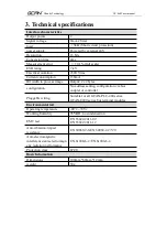
Page 3: ...The signal voltage is 0mA 20mA Powered by external 24V The load is greater than 5k short circuit protection Measurement error is less than 0 1 full scale The measurement resolution is 16 bits Convers...

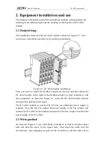
Page 4: ...ttach the GC 4642 module to the right of the fieldbus coupler or other modules to add this component As shown in Figure 2 1 insert the GC 4642 module inwards along the slot until the latch snaps The G...

Page 5: ...le installation Figure 2 3 GC 4642 module terminal block The terminal block of GC 4642 module is shown in Figure 2 3 GC 4642 contains 2 sets of output points and can connect up to 2 sets of analog sig...

Page 6: ...signal activation not bright Output signal is not activated Table 2 3 GC 4642 module indicator status 2 4 Use in combination with PLC400 510 series GCAN PLC 400 510 supports programming in five langua...

Page 7: ...of the output module then no matter how many input modules are in front the address of the first output module is still Q0 0 2 5 Combination with GCAN IO 8000 series equipment The status of the analo...

Page 8: ...image Output 2 x2 bytes configuration No address setting configuration via bus coupler or controller Pluggable wiring Suitable for all GCAN PLC 400 series GCAN 8000 series bus terminal modules Environ...

Page 9: ...efully Once used it is deemed to be an endorsement and acceptance of the entire content of this statement Please strictly abide by the manual product description and related laws regulations policies...

Page 10: ...CAN Digital input GC 1008 Digital input PNP 24V DC 8 channel GC 1018 Digital input NPN 24V DC 8 channel GC 1502 Counter 200kHz max 2 channel Digital output GC 2008 Digital output PNP 24V DC 8 channel...

Page 11: ...6 bits 10V 10V 2 channel GC 4642 Current output 16 bits 0 20mA 2 channel GC 4652 Current output 16 bits 4 20mA 2 channel GC 4662 Voltage output 16 bits 0 5V 2 channel GC 4672 Voltage output 16 bits 0...

Page 12: ...manual Sales and service Shenyang Vhandy Technology Co Ltd Address No 135 21 Changqing Street Hunnan Shenyang Liaoning China E mail sygckj gmail com Tel Whatsapp 86 13644001762 Skype live sygckj WeCh...

Reviews: