background image

Vhandy Technology

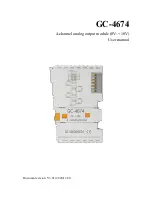
GC-4674 user manual

2.1 Module fixing

The installation method of GC-4674 module is shown in Figure 2.1. You need to use
a flat-blade screwdriver to assist in installation.

Figure 2.1 GC-4674 module installation

First, you need to install the fieldbus coupler on the rail, and then attach the GC-4674
module to the right side of the fieldbus coupler or other modules to add this
component. Please insert the GC-4674 module inward along the slot as shown in
Figure 2.1 until the lock catches.
The GC-4674 module is powered by GC-bus, no additional power supply is required.
You only need to connect the power supply to the bus coupler and connect the
GC-4674 to the module composed of the bus coupler to realize the power supply of
the GC-4674.

2.2 Wiring method

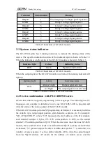
As shown in Figure 2.2, first insert a flat-blade screwdriver into the square hole and
hold the screw in the square hole. Then insert the cable into the circular hole. After
plugging it in, pull out the screwdriver and the cable can be firmly locked in the
circular hole.

Summary of Contents for GC-4674

Page 1: ...GC 4674 4 channel analog output module 0V 10V User manual Document version V3 01 2020 12 21...

Page 2: ...3 1 3 Typical application 3 2 Equipment installation and use 3 2 1 Module fixing 4 2 2 Wiring method 4 2 3 System status indicator 6 2 4 Use in combination with PLC400 510 series 6 2 5 Combination wi...

Page 3: ...less than 0 1 full scale The measurement resolution is 12 bits The conversion time is about 4ms The electrical isolation is 1500 Vrms GC bus signal voltage GC bus current consumption is 150mA The bit...

Page 4: ...e GC 4674 module inward along the slot as shown in Figure 2 1 until the lock catches The GC 4674 module is powered by GC bus no additional power supply is required You only need to connect the power s...

Page 5: ...4674 module wiring terminal block The wiring terminal block of GC 4674 module is shown in Figure 2 3 GC 4674 contains 2 groups of output points and can connect to 2 groups of analog signals at most T...

Page 6: ...icator light Colour Indicating status RUN Always bright Output signal activated not bright The output signal is not activated Table 2 3 Indicator status of GC 4674 module 2 4 Use in combination with P...

Page 7: ...in front the address of the first output module is still Q0 0 2 5 Combination with GCAN IO 8000 series equipment The status of the analog output is represented by two bytes For example GCAN IO 8000 mo...

Page 8: ...e process image Output 2 x 2 bytes configuration No address setting configuration via bus coupler or controller Pluggable wiring Applicable to all GCAN PLC 400 series GCAN 8000 series Environmental te...

Page 9: ...efully Once used it is deemed to be an endorsement and acceptance of the entire content of this statement Please strictly abide by the manual product description and related laws regulations policies...

Page 10: ...CAN Digital input GC 1008 Digital input PNP 24V DC 8 channel GC 1018 Digital input NPN 24V DC 8 channel GC 1502 Counter 200kHz max 2 channel Digital output GC 2008 Digital output PNP 24V DC 8 channel...

Page 11: ...6 bits 10V 10V 2 channel GC 4642 Current output 16 bits 0 20mA 2 channel GC 4652 Current output 16 bits 4 20mA 2 channel GC 4662 Voltage output 16 bits 0 5V 2 channel GC 4672 Voltage output 16 bits 0...

Page 12: ...nual Sales and service Shenyang Vhandy Technology Co Ltd Address Room 401 D11 Block SISP Hunnan District Shenyang Liaoning China E mail sygckj gmail com Tel Whatsapp 86 13644001762 Skype live sygckj W...

Reviews: