8
SHENYANG GUANGCHENG TECHNOLOGY CO.,LTD.
USBCAN-II Pro
User Manual
Shenyang Guangcheng Technology CO.LTD.
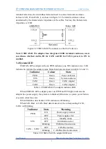
terminal reflection, the two furthest terminal need to connect terminal resistance
between CAN_H and CAN_L as shown in figure 3.2. Terminal resistance values
determined by the characteristic impedance of the cables. Such as, the characteristic
impedance is 120
Ω
.
Figure 3.2 USBCAN-II Pro connect to other CAN devices
Note: USBCAN-II Pro adapter
has integrated 120Ω
terminal resistance, users
can choose whether enable, R1 for CAN1 and R2 for CAN2, press it to ON to
enabled.
3.4 System LED
USBCAN-II Pro adapter with one PWR indicator, one SYS indicator, two CAN
indicator to indicate the adapter status. More functions are shown in table 3.2 and 3.3.
Indicator
Colour
State
PWR
Green
Power indicator
SYS
Green
System indicator
CAN1
Green
CAN1 singnal
CAN2
Green
CAN2 singnal
Table 3.2 USBCAN-II Pro adapter indicator LED
When USBCAN-II Pro adapter power on, PWR and SYS light, indicates the
adapter has power supply, the system is initialized; Otherwise, a system power failure
or system errors has exist.
When USB-Bus data transfer, SYS indicator will blinking.
When CAN-Bus1 or CAN-Bus2 data transceiver, the corresponding CAN1,
CAN2 will blinking.
Indicator
State
Meaning
PWR
ON
Power supply normal
OFF
Power supply error
SYS
ON
Standby mode
OFF
Initialization error
Blinking
USB data transmission
CAN1
、
CAN2
OFF
CAN-Bus no data
Blinking
CAN-Bus data transmission
Table 3.3 USBCAN-II Pro adapter LED state


