background image


Expert 52 User Manual


Installation                                                                              2-8 


Step 4   

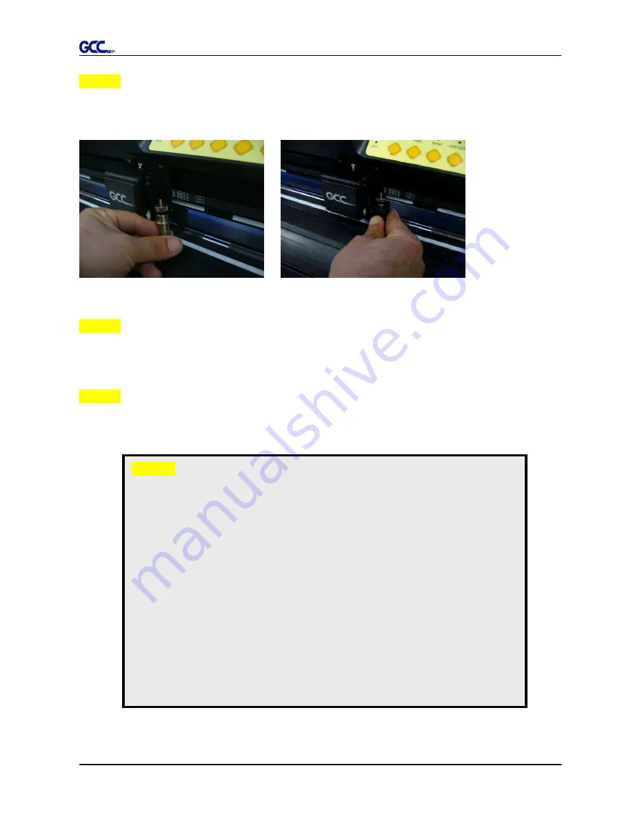
Insert the blade holder into tool carriage. Please note the outward ring of the holder must put 

into the grooves of carriage firmly (see Figure 2-11), fasten the case (Figure 2-12). 


Figure 2-11 


Figure 2-12     


Step 5     

Use the reversing steps to remove the blade holder. 


Step 6     

Eject the blade: Push “Blade eject pin” to eject blade when the blade needs to be replaced.     


Caution


The blade will lose its sharpness after a period of usage, the cutting quality might 

be affected. By increasing the cutting force, it might do the trick. However, once 

the blade is worn out and no longer provides a reliable cutting, you should replace 

a new one. The blade is consumable and must be replaced as often as necessary 

to  maintain  the  cutting  quality.  The  quality  of  the  blade  deeply  affects  cutting 

quality. So be sure to use a high quality blade to ensure good cutting results.


Tips - When to replace a new blade: 


If the blade is broken, you have to replace a new one. 


If cutting quality is not as good as usual, you may need to replace a new 

one. 


If the material cannot be cut through by higher cutting force, you may need 

to replace a new one.   

Summary of Contents for Expert 52

Page 1: ...V 6 2014 Mar EXPERT 52 CUTTING PLOTTER User Manual Great Computer Corporation...

Page 2: ...y the information contained in this user manual at any time without prior notice un authorized modification copying distribution or display is prohibited All comments queries or suggestions concerning...

Page 3: ...ation do not touch any of the moving parts of this machine such as the carriage Also be careful to make sure that clothing and hair do not get caught Always connect the power cable to a grounded outle...

Page 4: ...ns 2 13 2 7 1 USB Interface 2 13 2 7 2 Driver Un installation 2 16 2 7 3 RS 232 Interface 2 19 2 7 4 Printer Sever Shared Setting 2 19 3 Operation 3 1 The Control Panel 3 1 3 2 VLCD 3 2 3 3 File Uploa...

Page 5: ...her assistance 1 2 Product Features The followings are the main features of the Expert 52 cutting plotters Dual port connectivity USB Serial interface Up to 250 gram cutting force Up to 400 mm per sec...

Page 6: ...ia C Alignment Ruler To align media with clear guideline marks D Tool Carriage Performs the cutting with the installed blade or pen E Blade Holder To hold the blade F Platen The surface for holding an...

Page 7: ...er Connector To insert the AC power cord L Fuse 3Amp M Power Switch To turn on or off the machine N USB Connector To connect the machine and a computer through a USB cable O Serial Interface Connector...

Page 8: ...any direction Keep enough space for the machine accessories and supplies Keep the working area stable avoiding severe vibration Keep the temperature between 15 and 30 60 86o F in the workshop Keep the...

Page 9: ...stand 1 Support for left side 1 Support for right side 1 Stand Beam 2 Bottom Stands with wheels 2 Sliding brackets for paper take up 1 Hex Wrench M5 4 28 Socket flat head screws M6 12L 1 Installation...

Page 10: ...he screws into the holes but do not tighten them at this step Step 4 Remove the cutting plotter from the carton Position the stand under the plotter and insert the screws into the holes on the bottom...

Page 11: ...them up as shown in Figure 2 4 You could decide roll holder support s position by inserting into different holes Step 6 Place two roll holders onto the roll holder support and ensure the white protrus...

Page 12: ...ound three times after unpacking roll holder 2 Step 8 Insert the end of the roll holder without the damper into the left roll holder support and then insert the end of the roll holder with the damper...

Page 13: ...er Manual Installation 2 6 Step 9 Tighten the screw on the damper until it is securely attached to the right roll holder support Step 10 Lastly the complete picture will be shown like below Figure 2 6...

Page 14: ...tep 2 Install blade Figure 2 8 Push the blade to the bottom of the blade holder Figure 2 9 Step 3 Adjust the blade tip to suitable length by screwing Blade tip adjustment screw clockwise or count cloc...

Page 15: ...ng quality might be affected By increasing the cutting force it might do the trick However once the blade is worn out and no longer provides a reliable cutting you should replace a new one The blade i...

Page 16: ...l Installation 2 9 2 4 Instruction of Damper Roller Turn the wheel as instructed below to adjust damping The bigger the number is the stronger the damping The volume symbol sticker indicates the dampi...

Page 17: ...2 13 Step 2 Load your media on the platen and slide it under the pinch rollers from either the front side or the backside The alignment rulers on the platen extension will help you to adjust the media...

Page 18: ...ndary Pinch Roller at the center of media Note Expert 24 serves as an illustrator here Pinch Roller Figure 2 17 Figure 2 18 Primary Pinch Roller Figure 2 17 X Incorrect O Correct Secondary Pinch Rolle...

Page 19: ...e on line press origin set once and the red error light will start blinking then pressed again and the machine will start moving to get the new size Then open the VLCD and under the poll size you will...

Page 20: ...evision 1 1 Operation system of Windows 95 Windows NT don t support USB USB driver installation Use the USB One click Installation for quick driver installation Follow the simple steps below for drive...

Page 21: ...before you start the driver installation 2 Choose the model you want to install from the driver list and click on Win 8 7 Vista XP Driver Manual Selection or Win 8 7 Vista XP Driver Automatic detectio...

Page 22: ...driver is being installed for a second time the user will be prompted as to whether a second copy of the driver installation is required 2 If the user selects yes a second copy of the driver will be...

Page 23: ...installation You have to remove previous version driver installed on your PC system completely before you can install the latest version successfully Please refer to below steps 1 Right click on the...

Page 24: ...Expert 52 User Manual Installation 2 17 2 After removing the unit right click on any empty space on the page and select Server Property 3 Select Driver page...

Page 25: ...Expert 52 User Manual Installation 2 18 Select the model and click on Remove Click on OK Click on Yes The driver installed on PC is completely removed...

Page 26: ...assigned serial port COM1 or COM2 of your host computer 2 6 4 Printer Sever Shared Setting In A PC set the printer driver as a shared printer then use B PC to connect A PC s printer driver via interne...

Page 27: ...Installation 2 20 Step 2 Click Advanced tab then choose Print directly to the printer option Step 3 Send a job to the machine to check if A PC is connected to the machine Try to send a job to check i...

Page 28: ...Expert 52 User Manual Installation 2 21 Step 4 Activate A PC s Printer Driver from B PC s Network Step 5 Right click on printer icon and select Connect to connect A PC s printer...

Page 29: ...PAUSE keys activated While in off line mode the settings in VLCD can be adjusted PAUSE To temporarily halt cutting process or to continue REPEAT To repeat last job DATA CLEAR To clear up buffer memor...

Page 30: ...iage to a preferred position re set origin and then perform this function 3 2 VLCD VLCD is a computer program to help modify parameters of cutting functions 3 2 1 Installation Step 1 Copy the VLCD exe...

Page 31: ...2 Make sure no other devices are occupying the port that you are going to use Step 4 Press the Connect button to connect your computer and the cutter If the connection succeeds the model info firmware...

Page 32: ...3 4 Force To adjust the blade force between 0 and 250 Default 50 Media Weight To choose different weights of media in two options Heavy and Light Default Offset To adjust the blade offset to ensure cu...

Page 33: ...Pause 2 after On Off line 1 and then press Origin Set 3 Step 2 Press the left key 4 and then up 5 Step 3 You have now entered the Data clear and restoring default settings mode press Data clear 6 and...

Page 34: ...ion CD onto your local drive to finish installation Launch GCC File Uploader by double click on the icon Figure 3 5 3 3 2 Functions of File Uploader Port setup This function will be activated while ch...

Page 35: ...lotter Option 1 With proper interface settings the data can be transmitted from your application software package to the cutting plotters directly Option 2 Most cutting software packages are able to e...

Page 36: ...will be tagged with the Expert 52 series extension LOAD This function allows you to load previously saved print driver parameters ORIGINAL This function will load the print driver s original factory p...

Page 37: ...Expert 52 user manual Operation 3 9 Figure 3 7 Figure 3 8 Cutting line Vinyl...

Page 38: ...rce and offset in the section on the top following normal operating procedures see figure 3 10 Note 1 The extension of the blade has to be set to cut through both the top layer and the backing in the...

Page 39: ...Material Vehicle stickers Reflective film Cardboard Blade red green green Blade tip length mm 0 27 0 5 0 3 Force g 85 380 165 Speed cm sec 60 3 30 Offset mm 0 275 0 5 0 5 Recommend model RX Jaguar Pum...

Page 40: ...pe all the dust and dirt from the tool carriage rail Use a vacuum cleaner to clean any accumulated dirt and media residue beneath the pinch roller housing Clean the platen paper sensors and the pinch...

Page 41: ...int free cloth or cotton swab to wipe away the accumulated dust from the rubber portion of the pinch rollers To prevent the pinch rollers from rotating while cleaning use your fingers to hold the pinc...

Page 42: ...heck the following items first Solutions If the POWER LED lights on the cutting plotter should be in a normal condition Turn off the cutting plotter and turn it on again to see if the problem still ex...

Page 43: ...aph is clipped This condition indicates that the cutting graph is bigger than the cutting area You can solve the problem by 1 Reload a wider or longer media 2 Move the pinch rollers to widen the cutti...

Page 44: ...ts 1 stop bit Then press ON OFF Line key to switch back to On Line mode Warning 6 Width sensor error Check that the pinch rollers are positioned above the grid drum and reload the media again 5 2 2 Er...

Page 45: ...rking normally and see that the media is well loaded Then turn on the power and reboot the cutting plotter Error 4 Check the media or Y motor carriage driven motor This message indicates that there mi...

Page 46: ...an optimum blade force Refer to Chapter 4 3 Cutting Force and Offset Adjustment Is the tool offset set up properly Yes No Adjust the tool offset to obtain an optimum value Is there any dirt adhered t...

Page 47: ...Full Speed RS 232 Commands HPGL HPGL 2 Configurable Origin Yes Control Panel 6 LEDs 10 Keys Stand Standard Temperature 15 C 30 C 60 F 86 F Operation Environment Humidity 25 75 Compatible with Windows...

Page 48: ...arp edge 265012020G The blade is 60 with Green Cap 0 50 mm blade offset For cutting thin sandblast mask and stencil with friction feed or sprocket feed machine 26500059G The blade is 60 with Blue Cap...

Page 49: ...g to the reference point OFFSET is the distance that the blade tip is displaced from the centerline of the blade Protrusion Length of the Blade Length of protrusion t1 t 2 2 but for your convenience y...

Page 50: ...ile with CorelDRAW User Instructions 1 Open CorelDRAW finish editing all the files you wish to plot and select all the images at once 2 Select Outline Pen to adjust the outline for cutting 3 Adjust th...

Page 51: ...Expert 52 User Manual CorelDRAW Plug In A 1 4 Select File Print to output the file to your cutters 5 Choose the correct model you have installed...

Page 52: ...out page and click the Reposition images to Bottom left corner Please note that you must put your image at the bottom left corner 7 Go back to the General page and check that your image is at the bott...

Page 53: ...on your MAC you may need Parallels Desktop software Window OS and Windows based Adobe Illustrator CS6 to install Windows OS in your MAC computer and run Windows based software under MAC computer User...

Page 54: ...h this dialog below Step 2 Create import your image file For texts 1 Enter your texts in Adobe Illustrator select the letters and click Text outline to outline the letters A contour line will be creat...

Page 55: ...DriectCut A 4 For Images 1 Open a new image on Illustrator and decide the size of your material 2 Select the image and click Make outline and offset to create outlines of graphics Outlines will be cr...

Page 56: ...User Manual DriectCut A 4 3 Click on the image and apply the AAS function by clicking the Add registration marks command and select the registration marks needed The registration marks will be created...

Page 57: ...DriectCut A 4 Step 3 Output 1 Click on Plotter Setup and select the correct model in Plotter List 2 Tick Default Environment to create Pen No 1 in the Pen section Double click Pen No 1 and complete yo...

Page 58: ...Expert 52 User Manual DriectCut A 4 3 Select the entire object and click Plotter Output 4 Output the object by clicking Export and GCC Cutting Plotter will start cutting the image...

Reviews: