20
232001260G(10)
Chapter IV - Setup and Installation
4.1 Machine Setup
4.1.1 Powering Up the Machine
CAUTION
Make sure both the LaserPro X500SERIES and computer are turned off before
connecting either to a power source.
1) Connect the power cord to a quality surge protector and then connect the surge protector to a
properly grounded outlet.
Do the same for the computer system.
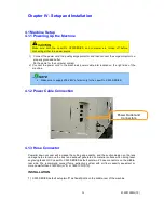
2) Connect the power cord in the machine’s power cable inlet located on the right side of the
machine
NOTE
•
Make sure to supply 200-240V of electricity to the LaserPro X500 SERIES
4.1.2 Power Cable Connection
4.1.3 Hose Connector
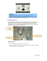
Powerful down vacuum will increase the cutting edge quality, and the suction design on the lens
carriage helps to remove the dust and exhaust generated on material surface when doing laser
engraving tasks. GCC LaserPro X500 SERIES default sets two 8” hose connectors on the middle-
rear side. We recommend connect fume extraction system with air flow capacity equivalent or
more powerful than 2160CMH (m
3
/h) or 76291CFH(ft
3
/h).
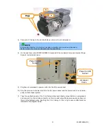
INSTALLATION
1)
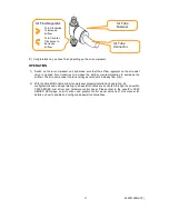
X500 SERIES default setup two
8” exhaust ports
on the middle-rear of the machine
.
Power Outlet and
Connectors
Summary of Contents for LaserPro X500 III-80Y
Page 1: ...0 232001260G 10...
Page 7: ...6 232001260G 10...
Page 8: ...7 232001260G 10...
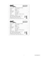
Page 9: ...8 232001260G 10 CDRH Label This label indicates the class level of CDRH...
Page 31: ...30 232001260G 10...
Page 32: ...31 232001260G 10...
Page 37: ...36 232001260G 10...
Page 38: ...37 232001260G 10...
Page 82: ...232001260G 10 81...
Page 83: ...232001260G 10 82...
Page 103: ...232001260G 10 102 Step 1 Produce the gray level background...
Page 105: ...232001260G 10 104 Step 2 Produce three dimensional characters...


