1-3 side view of Puma II
1 2 3
4 5 6 7 8
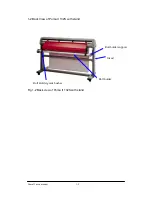
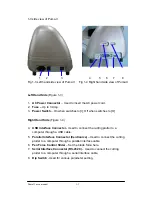
Fig 1-3 Left hand side view of Puma II
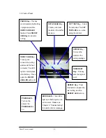
Fig 1-4 Right hand side view of Puma II
Left Hand Side
(Figure 1-3)
1.
AC Power Connector
– Used to insert the AC power cord.
2.
Fuse –
Up to 3 Amp.
3.
Power Switch
– On when switches to [I]; Off when switches to [O]
Right Hand Side
(Figure 1-4)
4.
USB interface Connector -
Used to connect the cutting plotter to a
computer through a USB cable.
5.
Parallel Interface Connector (Centronics)
– Used to connect the cutting
plotter to a computer through a parallel interface cable.
6.
Pen Force Control Slider
– Set the blade force here.
7.
Serial Interface Connector (RS-232C)
– Used to connect the cutting
plotter to a computer through a serial interface cable.
8.
Dip Switch
- Used for various parameter setting.
Puma II users manual 1-3
Summary of Contents for PII-132S
Page 1: ...Puma II users manual...


