background image


21 

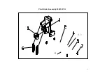
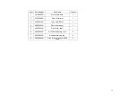
Main Beam Assembly 29005449G 


Item 

Part Number 

Part Name 

Quality 

22802169G 

Main beam Puma III-60 

21700021G 

Bearing Support 

29005441G 

Grid Drum Assembly 

24402320G 

Paper platten 

24000543G 

SPACE PE styrofoam - Puma III 


22200040G 

DC FAN(AD7524UB LF) 


Summary of Contents for Puma Series

Page 1: ...and stand on a dry surface If during the use of electrical equipment you feel an electrical discharge e g a tickling sensation on your skin immediately stop using that tool Label it and send it for re...

Page 2: ...tenance 30 Removing the Front Back End and Top Covers 30 Replacing the Pinch Roller Sets 32 Replacing the Tool Carriage 34 Replacing the Y Motor 36 Replacing the VCM PC Board 38 Main board Connection...

Page 3: ...ring diagrams and numerous flow charts detailing the maintenance diagnostics built into the Expert Pro Cutting plotter Finally there is a parts list and spare parts order form for convenience of order...

Page 4: ...4 Main Unit Assembly 29006178G...

Page 5: ...ly 1 5 22800705G Top rail 1 6 22801070G Square Bar 1 7 29001473G Pinch roller assembly 2 8 29004690G Carriage assembly 1 9 22802168G Top cover 1 10 24100499G Left cover 1 11 24100491G Right cover 1 12...

Page 6: ...Assembly 29004693G Item Part Number Part Name Quality 1 24401210G Unit base box 1 2 29005498G Main board 1 3 29001488G Power board 1 4 25700075G ON OFF Power switch 1 5 22300021G Fuse holder 1 6 21800...

Page 7: ...7 Left End Assembly 7 1...

Page 8: ...ity 1 29003810G X Axis Motor Assembly 1 2 24100189G X Axis actively belt gear 1 3 20600039G X Axis belt 1 4 24100175G Idle pulley 1 5 24400288G X motor adjusting bracket 1 6 24400761G X motor bracket...

Page 9: ...9 Right End Assembly 7 8...

Page 10: ...24400264G Active pulley s bracket 1 2 24100176G Active pulley 1 3 22800288G Active pully s shaft 1 4 24400066G Cable basket 1 5 24400265G Y motor bracket 1 6 29003812G Y Motor Assembly 1 7 24100258G...

Page 11: ...20200085G Blade holder slider bracket assembly 1 5 29000940G VCM assembly 1 6 20200065G VCM coil 1 7 25500043G Tool carriage spring 2 8 29001467G VCM PCB assembly 1 9 22800838G Blade holder bracket sc...

Page 12: ...029G Bearing 4 16 22800710G Carriage guide roller flute 4 17 22801464G White spring bracket for carriage guide roller 2 18 25500041G Spring for carriage guide roller 4 19 22800717G Carriage guide roll...

Page 13: ...13 Complete X motor Assembly 29003820G...

Page 14: ...14 Item Part Number Part Name Quality 6 1 29003820G Motor assembly 1 6 1 1 29003810G Motor 1 6 2 24400761G X motor bracket 1 6 3 24400288G X motor adjusting bracket 1...

Page 15: ...15 Y Axis Idel Pulley Assembly 29003820G...

Page 16: ...4900006G E shape retaining ring 4 8 1 5 22801465G White pulley Washer 1 8 1 6 25200345G M3 14 Pan Screw Spring 1 8 1 7 23500004G Nut M3xt2 4xS5 5 1 8 2 24400287G Idle pulley Assembly adjusting bracket...

Page 17: ...17 Pinch Roller Assembly 29001437G 4 1 8...

Page 18: ...r base 1 2 24100286G Pinch roller arm 1 3 22800310G Lynx Cam Roller 1 4 20200003G Pinch roller wheel 1 5 22800029G Pinch roller shaft 1 6 25500040G Pinch Roller Spring Lynx 2 7 24900006G E shape retai...

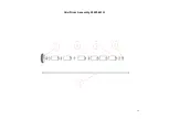
Page 19: ...19 Grid Drum Assembly 29005441G...

Page 20: ...em Part Number Part Name Quality 1 22802167G Grid Drum shaft Puma III 60 1 2 22800564G Bearing Blocker 2 3 20700039G Bearing L 1910ZZ 5 4 23300362G long drum 50mm 6 5 24100189G X axis actively belt ge...

Page 21: ...tem Part Number Part Name Quality 1 22802169G Main beam Puma III 60 1 2 21700021G Bearing Support 5 3 29005441G Grid Drum Assembly 1 4 24402320G Paper platten 1 5 24000543G SPACE PE styrofoam Puma III...

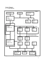
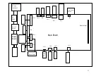
Page 22: ...22 1 System Diagram and Components of Main Board...

Page 23: ...206EFT54 FPGA SRAM 64K 32Bit DRAM 16MB TIMER PWM Generator X Motor Driver Y Motor Driver VCM Driver Driver System Feedback Sensor Motor Phase Decoder X Motor Encoder Y Motor Encoder Direction Control...

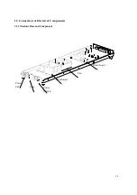
Page 24: ...24 1 2 Connection of Electrical Components 1 2 1 Machine Base and Components Main board Fan Power Cable Fuse Power Switch Transformer...

Page 25: ...5 J JP15 AC Input 100V 240V Front Paper Sensor 3A FUSE JP38 JP10 JP8 JP7 JP15 JP14 JP19 U5 On Off Switch JP39 DRAM SIMM Power Board JP18 Main Board JP13 JP40 JP12 JP16 JP17 JP11 Control Panel Lever SW...

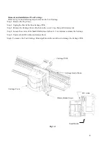
Page 26: ...e the two screws that fix the bracket to the carriage guide beam 2 Remove Pinch Roller Set Step 1 Move the Pincher Roller Set to the furtherest end view from rear where a notch is on the guide beam St...

Page 27: ...he Lever If you just need to replace Lever please refer to Step 3 to install the Lever Assembly please make sure Switch Cam and Lever Switch are well positioned then follow by Step 3a Lever is down St...

Page 28: ...e Carriage Cover Push down the cover s top then pull it downward Step 4 Loosen the screws of the Small Roller lower about 2 3 revolutions to release the Carriage Step 5 Unscrew both DU rollers and rem...

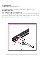
Page 29: ...e to one end of the guide beam Step 2 First place the top arm gauge in the top track of guide beam Then the bottom arm will click into the bottom track see Fig 1 5 Step 3 Make the white cylinder is fl...

Page 30: ...on on how to replace or adjust the components of this machine Components Replacement and Belt Tension Adjustment Removing the Front Back End and Top Covers The following steps are those involved in re...

Page 31: ...nt and Back Covers 1 Unscrew the 7 Front Cover and 7 Back Cover screws Remove the Top Cover 1 Unscrew the two screws at each end of the Top Cover 2 Unplug the Control Panel Cable before removing the t...

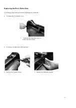
Page 32: ...ps are those involved in replacing pinch roller sets To Unlatch the Pinch Roller Lever 1 Pull down the Square Bar Lever to unlatch the Pinch Rollers To Remove the Square Bar Holding Bracket 2 Unscrew...

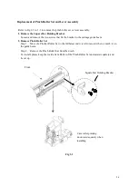
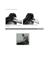
Page 33: ...Sets 3 Slide the pinch roller to the notch at the right end of the Square Bar 3 Remove the pinch roller set through the notch Note When re installing the Pinch Roller Set the Cam Roller must be align...

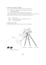
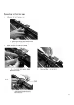
Page 34: ...rriage cover 1 Depress the two locking clips at the top of the Tool Carriage Cover and pull the Cover away To Prepare the Tool Carriage for Removal 1 Pop up the plastic locking pins using a flathead s...

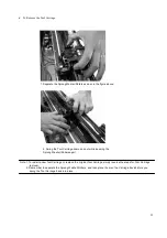
Page 35: ...n and out while keeping the Sprung Washer Rollers apart Note 1 To install a new Tool Carriage or replace the original Tool Carriage simply reverse the steps for Tool Carriage removal 2 Remember to sep...

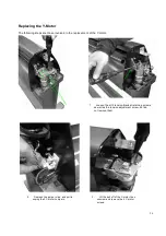
Page 36: ...nt of the Y motor 1 Loosen the all 3 tension bracket retaining screws as well as the tension adjustment screw but do not remove them 2 Depress the jumper clips and pull to unplug the 2 Y motor Jumpers...

Page 37: ...e Y motor is in place you must adjust the Y motor belt tension as described in the Y motor belt tension adjustment section of this chapter Note 3 Make the Y motor jumper reconnection the last step aft...

Page 38: ...d in replacement of the VCM PC board 1 Unplug the two sensor connectors and then unscrew the two PC board screws to remove the board Note If the Pinch Roller Sensor is still not effective after replac...

Page 39: ...e follow the safety instruction at the beginning of this manual before installing or replacing any current carrying components T Parallel Port Connector o unplug the jumpers and connectors from the ma...

Page 40: ...e main board Note To install or replace the main board simply reverse the steps to remove it Replacement of Fuses The Fuse pops out for easy replacement as follows Holding clip Holding clip 1 With you...

Page 41: ...Use a tension gauge to measure the belt s tension by placing the gauge s push arm to the center of the belt as seen in the figure above 4 To change belt tension adjust the belt tension screw on the s...

Page 42: ...ook arm at the hole of X motor bracket and pull the motor toward yourself along the direction parallel to the racket edge and keep it at the 4kg tension position 3 Tighten the 4 retaining screws to lo...

Page 43: ...ve them 2 Place the push pull tension gauge s hook arm at the hole of Y motor bracket and pull the motor toward yourself along the direction parallel to the line that passes through the motor shaft an...

Page 44: ...44 4 Tighten the tension screw to retain the tension Note The belt connecting the pulley and Y motor needs to be tightened up with a tension of 4 kg...

Page 45: ...sing this diagnostic test facility enables the diagnosing of the hardware components How to Begin Maintenance Diagnostics Diagnostic test for the media sensors Diagnostic test for the width sensor Dia...

Page 46: ...agnostics To start the Maintenance Diagnostics facility hold down the On Off Line button and CUT TEST button while turning on the cutter The following sub sections will explain the function of each ma...

Page 47: ...ch rollers have been lowered or not If the lever sensor is down you will see a lift the lever message on the LCM If the lever is up you will see a lower the lever message on the LCM You can use the ON...

Page 48: ...ent front and rear sensor condition you can turn it on or off to see if sensors are out of order or not Cancel Key Previous Next Test item Display Current Sensor Condition Messages Change Sensor Condi...

Page 49: ...e please move the tool carriage to left Be careful when moving the tool carriage close to the pinch roller since the message changes quickly when sensor is between on and off Check Width Sensor Enter...

Page 50: ...s defective the cutting plotter cannot work properly To check if the encoder is bad or good you can apply a slight force to the tested part such as a drum the tool carriage or the tool holder then exa...

Page 51: ...M means Voice Coil Motor that generates tool force Diagnostic Test for Motor Movement This feature is to diagnose the X and Y motors and drIIIers If you encounter a motor movement problem try to chang...

Page 52: ...t test item Carriage Goes Left Up Down Key Cancel Key Enter Key Y Motor Moving Now Forward CANCEL Previous Next test item Carriage Goes Right Up Down Key Cancel Key Enter Key Y Motor Moving Now Backwa...

Page 53: ...t press keys too quickly or it may cause an overrun error Diagnostic Test for the RS 232 Interface This feature provides the ability to diagnose RS 232 interface and checks communication between the c...

Page 54: ...CB set is damaged Change carriage set The function of Set New Origin does not work Causation and recovery The origin point will be set by pressing the ENTER button when the Puma is in an OFFLINE state...

Page 55: ...t the carriage belt tension The drIIIer board set is damaged Change it The machine makes abnormal noise from the drum set when it is running Causation and recovery X or Y motor belt is loose Adjust th...

Page 56: ...force setting is wrong Reset the initial force please contact the manufacturer VCM is damaged Change the carriage set VCM encoder is damaged Change the carriage set Media drops sometimes Causation and...

Page 57: ...57 Appendix Parts and Accessory List Spare Parts Customer Service Request Form To the Contents Page...

Page 58: ...Part Name Qty Payment U Price Ship date F O B F O C SAS US 195 00 F O B F O C SAS F O B F O C SAS F O B F O C SAS F O B F O C SAS F O B F O C SAS F O B F O C SAS F O B F O C SAS F O B F O C SAS F O B...

Reviews: