3
Introduction and Component
Overview
This Maintenance Guide provides step-by-step instructions for replacing and maintaining the
components of the Puma Cutting plotter. It also includes a troubleshooting chapter
with some handy hints when problems arise or if the plotter does not operate properly.
This Maintenance Guide provides system diagrams, wiring diagrams and numerous flow
charts detailing the maintenance diagnostics built into the Expert Pro Cutting plotter.
Finally
there is a parts list and spare parts order form for convenience of ordering replacement parts.
For further Tech Support enquiries and assistance please contact the following Email
address:
Tech.support@gcc.com.tw
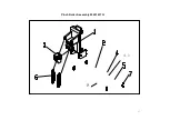
The following diagrams represent all of the maintainable mechanical and electronic
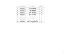
components of the Expert Pro Cutting Plotter with corresponding parts lists for
convenient identification.
To the Contents Page
Summary of Contents for Puma Series
Page 4: ...4 Main Unit Assembly 29006178G...
Page 7: ...7 Left End Assembly 7 1...
Page 9: ...9 Right End Assembly 7 8...
Page 13: ...13 Complete X motor Assembly 29003820G...
Page 15: ...15 Y Axis Idel Pulley Assembly 29003820G...
Page 17: ...17 Pinch Roller Assembly 29001437G 4 1 8...
Page 19: ...19 Grid Drum Assembly 29005441G...
Page 22: ...22 1 System Diagram and Components of Main Board...


