

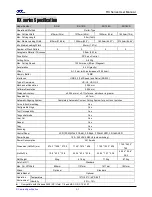

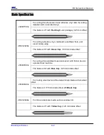
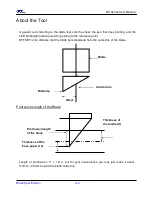
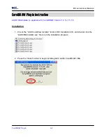


RX Series User Manua
l
Trouble Shooting 7-2
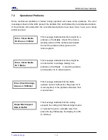
7.2 Operational Problems
Some mechanical problems or failure during operation will cause some problems. The error
messages shown on the LCM present the problem first, and followed by recommended actions.
If the problem still exists after the recommended actions have been done, have your cutting
plotter serviced.
Error, Check Media
Or Drum or X Motor
This message indicates that there might be a
problem on the X axis. Check if the drum is
working well and if the media is well loaded.
Correct the problem and re-power on to
reboot system.
Error, Check Media
Or Y Motor
This message indicates that there might be
an obstruction to carriage relating to a
problem on the Y axis. Correct the problem
and re-power on to reboot system
.
Error, Check Carriage
Sensor or VC Motor
This message indicates that the blade
up/down sensor malfunction. Re-power on to
re-boot system. If the problem still exists, find
a serviceman.
Graph Was Clipped.
Data In Buffer
This message indicates that the cutting
exceeds the cutting limit. Reload larger media
or re-scale the plot to a smaller size; then
press the key followed by the display of LCM
to continue.
Summary of Contents for RX Series
Page 1: ...V 7 2014 Mar RX Series User Manual http www GCCworld com ...
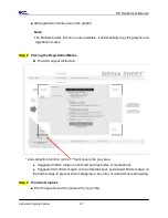
Page 33: ...RX Series User Manual Installation 2 20 3 Select Driver page ...
Page 48: ...RX Series User Manual The Control Panel 3 3 3 2 Menu in On line Mode ...
Page 49: ...RX Series User Manual The Control Panel 3 4 3 3 Menu in Off line Mode ...
Page 50: ...RX Series User Manual The Control Panel 3 5 ...
Page 51: ...RX Series User Manual The Control Panel 3 6 ...
Page 115: ...RX Series User Manual SignPal 10 5 Instruction A 4 8 ...
Page 118: ...RX Series User Manual SignPal 10 5 Instruction A 4 11 ...
Page 125: ...RX Series User Manual SignPal 10 5 Instruction A 4 18 ...
Page 155: ...Jaguar IV User Manual GreatCut Instruction A 5 Click Multi Copy in GreatCut2 under File ...


