background image

4xx Preliminary Generic User Guide. 4 Jan 06

 10 

Load Compensation 

Normally this is set to 600 Ohm to match the line impedance.  
Switching to High increases the gain of the receiver and is only used when the 
receive signal is so low it causes data errors. 
 

KOD Function 

Data is used to key the modem On and Off when there is no RTS handshaking 
from an attached device.  
 

KOD Direction 

The KOD direction can be reversed and FSK can raise RTS at the modems 
data port. 


KOD Delay 

The time between the KOD generated RTS and when data occurs, note the 
same period of time occurs after data ceases to when RTS is lowered. 
Selectable time periods are 1.6, 3.3, 6.6 and 13ms. 


Anti- Streaming 

Anti streaming is a feature that prevents a modem connected to a 
malfunctioning controller from monopolizing and jamming up the 
communications path.  
As an example, in multi-drop, polled, environments a “Master” sends out a 
logical address and expects a response from the addressed device. If another 
unaddressed controller has raised RTS, this will cause its attached modem to 
broadcast a carrier tone which will “jam” all the modems on the line.  
The Ant-Streaming feature of the modem prevents this by limiting the amount 
of time that the modem can continuously transmit to around 7 seconds. If 
Request To Send remains continuously active for longer than this period, the 
modem will override the condition, and stop transmitting until RTS goes Low.  
 

External KOD On/Off Pin 9 

Disconnects Pin 9 to prevent potential conflict with controller RS232 Port 


Data Protocol 


RS232 

This is the standard format for the modem and is designed for short distance 
communications of less than 100ft and is ideal when connecting to the traffic 
controller or other devices within the cabinet.  
 

RS422/485

 is used to drive longer distances than RS232 over 2 pairs of 

balanced transmission lines; this is an option and must be specified at the time 
of order.


Summary of Contents for 4xxSA

Page 1: ... TI 4 Jan 06 GDI COMMUNICATIONS LLC PO Box 1330 280 I 80 Exit 1 Verdi NV 89439 Phone 775 345 8000 Fax 775 345 8010 Email support sgdi com Model 4xxSA Stand Alone FSK Modem USER GUIDE ...

Page 2: ...onse 5 Introduction to the 4xxSA Series of Modems 6 Model 4xxSA Modems 6 The KOD Option 6 Front Rear and Bottom Panels 7 Front Panel 7 Front Panel LED s 7 Rear Panel 8 Dual Data Ports 8 Copper FSK 8 Power Connections 8 Bottom Panel 9 DIP Switches 9 Full or Half Duplex 9 RTS to CTS Time 9 Carrier Turn Off Time 9 Local Echo 9 ...

Page 3: ...D Direction 10 KOD Delay 10 Anti Streaming 10 Data Protocol 10 RS232 10 RS422 10 Applications _________ ___11 Half Duplex Operation 2 Wire 11 Full Duplex Operation 4 Wire 12 Modems with the KOD Option Installed 13 Internal KOD 13 External KOD 13 KOD Applications 14 More Applications 15 Repeater Applications 16 A Word on Dynamic Range 17 Notes 18 ...

Page 4: ...rmat that is data is represented by either logic high or logic low 1 or 0 Communications terminology refers to logic Low as Mark and logic High as a Space FSK Modems utilize this fact and generate a unique frequency for each logic level Each model in the 4xx series have their own unique set of frequencies due to the baud rate therefore only modems of the same model number can communicate with each...

Page 5: ...elch and raise CD at the data port This CD signal advises the Controller to expect data The demodulated Mark tone logic 0 is passed to the RS232 Data port where it does not change state due to the fact that when not in use it is always at logic 0 same as the transmit end Now let s go back to the TMC end 3 Once the TMC computer receives CTS clear to send it will send data to the modem At this junct...

Page 6: ...t that when not in use it is always at logic 0 same as the Controller end Now let s go back to the Controller end 4 Once the Controller receives CTS clear to send it will send data to the modem At this juncture both modems on the system are in a go state 5 The Controller now sends data 0 s and 1 s to the modem which converts it to Mark and Space frequencies These frequencies tones are then transmi...

Page 7: ...RS422 485 is an option that must be specified at the time of order The Key On Data KOD Option Modems cannot raise or lower RTS or initiate handshaking the only exception to this rule are the new GDI Modems with an optional installed KOD Module All copper wire modems DCE require RTS to be raised at its data port to start the FSK transmission process over the copper wire This process is normally tak...

Page 8: ...andshaking and causes the modem to wake up and transmit a Mark signal over the 2 4 wire cable system CTS Clear To Send Output The Modem responds to the incoming RTS by raising CTS to the attached device after a selected delay of 6 or 12ms This is the second and final part of handshaking protocol TXD Transmit Data Input This indicates data activity from the Host device into the modems serial port R...

Page 9: ... as RS422 485 interface on appropriate model Copper FSK This is where the modem connects to the private wire metallic pairs generally referred to as copper The modem can operate in either 2 wire or 4 wire duplex modes Note that in 2 wire operation the cable pair is connected to the OUT terminals on all modems Power Connections The modem has a power cord with a standard AC Plug for 115VAC 60Hz alte...

Page 10: ...ch Time The length of time which the Soft Carrier detector has before disabling the receivers output to the digital circuits this can be set to 6 or 3ms Carrier Detect The length of time after carrier has been detected before enabling the receivers output to the digital circuits this can be set for 8 or 4ms Half Duplex RTS to Data Delay Full Duplex PIN 9 Half Duplex Normal RTS to CTS Time 12ms 6ms...

Page 11: ...p polled environments a Master sends out a logical address and expects a response from the addressed device If another unaddressed controller has raised RTS this will cause its attached modem to broadcast a carrier tone which will jam all the modems on the line The Ant Streaming feature of the modem prevents this by limiting the amount of time that the modem can continuously transmit to around 7 s...

Page 12: ... to a 4wire operation The DIP Switch diagram below is where the adjustments are made to operate in either 2 or 4 wire mode note also you can change various timing parameters The settings shown are for 2 Wire which is Half Duplex operation OUT IN OUT IN OUT IN TMC Host RS232 419 Modem 419 Modem 419 Modem Request Reply Request Reply Half Duplex RTS to Data Delay Full Duplex PIN 9 Half Duplex Normal ...

Page 13: ...nts are made to operate in the 4 wire mode note also you can change various timing parameters The settings shown are for 4 Wire which is Full Duplex operation OUT IN OUT IN OUT IN TMC Host RS232 419 Modem 419 Modem 419 Modem Half Duplex RTS to Data Delay Full Duplex PIN 9 Half Duplex Normal RTS to CTS Time 12ms 6ms Cxr Turnoff Time 10ms 5ms Local Echo Full Duplex Off On Rcr Squelch Time 6ms 3ms Cx...

Page 14: ...dem communications on the cable pair The solution is to install a KOD module Internal KOD With a KOD device installed data flowing from the radio arrives at the KOD module which in turn raises RTS to the modems input RTS raised now keys the modem on and data is then transmitted At the end of the data transmission the KOD device lowers RTS which turns off the modems transmitter carrier Now the tran...

Page 15: ... FSK Controller 1 Data Receive Pair 4Wire 4xx Plug in Modem IN OUT Radio TXD RXD S GND TXD RXD S GND Local Controller 1 Aux Port Main Port KOD KOD Direction Switched to Internal Radio Data City Hall Receive Pair Polled Response Modem Flow Diagram Local Controller 2 Keyed On Data Shared Path Controller 2 Controller 2 Controller 3 From Controllers xx 4Wire 4Wire 400 Series Modem IN OUT 400SA Modem I...

Page 16: ...ate in any mode such as A Daisy Chain as shown or Single Fiber Ring or Dual Counter Rotating Ring Self Healing Note GDI Modems Maximum Capabilities Local Controller 2 RXD 3 TXD 5 S GND Main Port Aux Port RTS CTS Optional 3 RXD 5 City Hall RS232 4xx Series Modem OUT IN Generic Fiber Optic Modem Generic Fiber Optic Modem Generic Modems Basic Capability 2 or 4 Wire to Fiber Generic Fiber Optic Modem ...

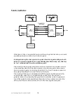
Page 17: ...ms together via Auxiliary Data Ports The Local Controller connects to the modems Main Data Port on the TMC City Hall side The incoming FSK tones are demodulated to RS232 signals and then passed to the second modem where they are modulated back to FSK tones This process is generally referred to as repeating the signal when in actuality we have regenerated clean FSK signals from the digital input Ba...

Page 18: ...s due to high levels or a short between adjacent pairs 5 Induced noise due to poor grounding of the cable cabinet 6 Baud Rates as the frequency goes up the transmission distance decreases 1200 baud may go 20 miles while 19200 baud on the same cable pair will typically be less than 10 miles Pushing the Envelope Making the Last Mile Additional distance can sometimes be obtained by boosting the gain ...

Page 19: ...may not be copied or published without the written consent of GDI Communications LLC Verdi Nevada The contents of this user guide are deemed to be correct at the time of publishing and are offered as a guide only GDI Communications LLC is not liable for any inaccuracies or omissions ...

Page 20: ...hed without the written consent of GDI Communications LLC Verdi Nevada The contents of this user guide are deemed to be correct at the time of publishing and are offered as a guide only GDI Communications LLC is not liable for any inaccuracies or omissions ...

Reviews: