11
Commissioning
•
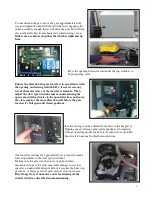
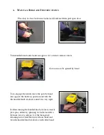
Position the gate halfway and tighten clutch (knurled knob on gearbox) just firm enough to drive the gate but still
allowing it to slip if the slow down switches aren’t adjusted correctly and the gate hits the mechanical stops at full
speed.
•
Power up board and with gate in the half way position, press transmitter or manual control switch so operator
drives gate.
•
The first pulse will always open gate, green LED will flash (top right hand corner) if it does not, then reverse 2 of
the motor wires.
The operator has been set up in the factory to open up to the left when looking at the gate
from the inside or secure side of the property, so in reversing the direction of the motor, the open and close
slow speed switch cams will have to be adjusted to match the new opening and closing directions.
•
Check that the slow speed switches are set correctly for the direction the gate is travelling in and adjust cams so
gate will slow down when approaching the fully open and closed positions.
Do not alter wiring connections
.
•
Once happy with the slow speed area settings tighten the clutch knurled knob very tight.
•
Set open & closed travel times as explained earlier.
•
Check that all safety devices work as designed and tested.
•
Install cover using screws provided in the front and sides to hold cover firm.
Provide full details to the owner concerning the operation and relevant maintenance and disconnect details.
Variable speed drive unit
•
The variable speed drive unit will, ramp up the speed of the operator and then ramp down prior to closing.
•
It must be remembered that the limit switches are to be set in a position which initiates the slow speed area time,
therefore the limit switches need to operate much sooner than when there is no variable speed drive unit.
•
The acceleration and deceleration times, open and close speed and slow speed area times have been set in the
factory for the normal installation but can be changed if necessary. Similarly, the speed that the gate operates at
has also been set but can be changed (up to approx 70Hz).
•
The gate stop current trip margin can be changed if required on a larger gate.
Navigating through inverter menu
•
From the main screen “0.00” press the PRG button twice to get to the parameter menu screen “P0.00”.
•
Use >> button to select required digit on screen to change then scroll that digit up or down with the up/down
↕
button.
•
Use up/down
↕
buttons to get to the required parameter number, once number selected, press “SET” to enter into
required parameter, once in, use the up/down
↕
buttons again to change the number.
•
Once parameter has been changed, the display will start flashing, while it`s flashing press set to enter the new
number. If that new entry has been accepted the display will stop flashing.
•
Press SET again to change back to the parameter menu screen.
•
Once finished with the changes, press PRG again return to main screen “0.00”.
•
FACTORY SET PARAMETER LIST ON NEXT PAGE.
Summary of Contents for GDS 450 W
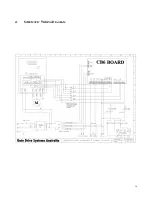
Page 14: ...14 4 SCHEMATIC WIRING DIAGRAM ...
Page 18: ......


