background image


1.


S

AFETY 

P

RECAUTIONS


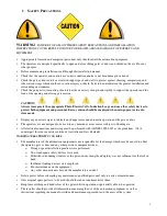
WARNING!


 FAILURE TO FOLLOW THESE SAFETY PRECAUTIONS AND INSTALLATION 

INSTRUCTIONS COULD RESULT IN INJURY OR DEATH AND

/

OR DAMAGE TO PROPERTY AND 

EQUIPMENT


Appropriately licensed and competent personnel only should install the automation equipment. 


The operators are designed specifically to open and close sliding gates or doors and should not be used for any 
other purpose. 


Before commencing installation, read through this installation manual. 


Check that the operator and controls are in new condition and have not been damaged in transit. 


Check the gate or door and it`s associated support posts and walls to protect against shearing, compression and 
other various traps which could cause serious injury or death. Take into consideration the general installation and 
surrounding environment. 


Check the gateposts or mounting structure has the necessary strength and rigidity to support the operator and the 
load of the opening and closing gate motion.


CAUTION!    


Always incorporate the appropriate Photo Electric Cells, Induction Loops and any other safety devices to 
protect both equipment and personnel. Extra caution should be employed when using operator in auto 
close mode.


Display any necessary signs to indicate any danger areas and automatic operation of the gate or door. 


The operators are not designed to be used in any hazardous areas or areas subject to flooding etc. 


All electrical connections and wiring must be performed with AS/NZS 3000-2007 as the guidelines. (Or its 
counterpart for other countries outside of Australia and New Zealand)  


WARNING! ELECTRICITY CAN KILL 


The manufacturer of the automation equipment is not responsible for the damage which may be caused to either 
the operator, gate or door and any other person or equipment when: - 

o


Wrong or poor installation practices were performed. 

o


No or inadequate safety devices were used. 

o


Either the surrounding structure or the gate or door strength and rigidity was not sufficient for the task in 
hand. 

o


Inefficient locking devices were employed. 

o


Poor maintenance on the equipment. 

o


Any other circumstances beyond the manufacturers control. 


Isolate power before attempting any maintenance, qualified personnel only to carry out maintenance 


Only original spare parts are to be used should there be a requirement for them.  


Keep loose clothing and hands clear of the gate whilst in operation or potentially able to be operated.


The installer should provide all information concerning the use of the automation equipment as well as 
instructions regarding the manual override and maintenance procedures to the users of the system.


Summary of Contents for GDS 450 W

Page 1: ...Installation and Maintenance Manual Sliding Gate Operators Inbuilt Models GDS 450 630 W Range Made in Australia from Australian quality imported components A B N 62 059 806 405 October 2013 N14870 ...

Page 2: ...ght the rack moving over the pinion wheel check that most of the pinion wheel meshes with the rack Make sure rack runs freely over the pinion wheel any tights spots should be corrected by adjusting the rack height Check the operator is firmly bolted down to the concrete pad Ensure adequate engineered stops are installed on the gate for the fully closed and fully open positions Connect required P E...

Page 3: ...switch activates in the open direction and so too the close cam for the close direction well before the gate reaches it s full open and closed positions Inverter settings can be adjusted if needed via the keypad i e Opening speed closing speed and ramp times Automation settings operating modes are able to be adjusted via the CB6 board refer to manual for further instructions Once inverter settings...

Page 4: ... Installation Wiring requirements Plan view of operator installation for conduit entry points CB6 Control Board CB6 inputs outputs and settings Variable Speed Drive Unit Commissioning Inverter parameter list Using inverter monitoring function parameters for fault finding 4 Schematic wiring diagram of controls 14 5 Manual release operation 15 6 Maintenance schedule 16 7 Warranty 17 ...

Page 5: ...y necessary signs to indicate any danger areas and automatic operation of the gate or door The operators are not designed to be used in any hazardous areas or areas subject to flooding etc All electrical connections and wiring must be performed with AS NZS 3000 2007 as the guidelines Or its counterpart for other countries outside of Australia and New Zealand WARNING ELECTRICITY CAN KILL The manufa...

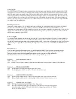
Page 6: ...es the mechanical stop Even if the gate ends up hitting the mechanical stop at full speed either the inverter will detect the sudden current rise and cut power to the motor in turn displaying a fault code on its display and the clutch will slip The Prostar inverter has an advanced function parameter list with a detailed list of monitoring display functions for both the operation of the inverter an...

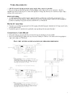
Page 7: ...ll provide measurements for the positioning of conduits and the appropriate position for mounting the operator whether a GDS 450 W or a GDS 630 W Electrical Connections Connect a non earth leakage protected 10A 240v supply to Din Rail terminals labelled A N Connect earth to the earth Din Rail terminal Conduits for power control need to preferably come up through the base plate knockout Connections...

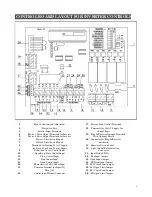
Page 8: ...ver 7 Motor 2 Limit Switch Inputs not shown 8 Terminals for Isolated 24vAC Supply 21 Firmware Version Label for Limit Switch and Control Inputs 22 Light Control Relay Interface 9 Pedestrian Access Control Input Connector 10 Open Stop Close Control Input 23 Input Status L E Ds 11 Close Control Input 24 Stop Input Jumper 12 Stop Control Input 25 Open Input Jumper 13 Open Control Input 26 PE Beam Inp...

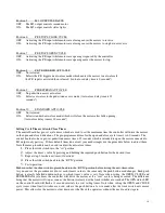
Page 9: ...itched by the lock output terminals must not exceed 30V A C D C 5Amps If an electromagnetic lock is used change one wire on the control board lock output to the normally closed output Use the light relay module if fitted to switch the applied voltage to a light The load switched by the light relay module must not exceed 240V A C 30V D C 10 Amps Mode Selection Using the mode selection dip switches ...

Page 10: ... cycle timer s is 60 seconds The control board also has a pre set pedestrian access time of 5 seconds which is intended to open the motor connected to M1 output only part way If these default times do not suit your needs simply use the procedure below to adjust them Note the same procedure can be used to adjust the auto close times 1 Place the slide switch into the set position 2 Adjust the timer ...

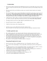
Page 11: ... operation and relevant maintenance and disconnect details Variable speed drive unit The variable speed drive unit will ramp up the speed of the operator and then ramp down prior to closing It must be remembered that the limit switches are to be set in a position which initiates the slow speed area time therefore the limit switches need to operate much sooner than when there is no variable speed d...

Page 12: ...voltage 230 P0 14 Acceleration time 5 0 P0 15 Deceleration time 2 5 P2 28 Closing speed 30 P4 00 Closing Speed Input terminal DI1 1 P4 01 Opening slow speed jog terminal DI2 9 P4 02 Closing slow speed jog terminal D13 10 P4 09 Programmable relay output Inverter overload alarm set 8 P4 13 Overload pre alarm Checkout level percent 60 P4 14 Overload pre alarm Delayed time 3 0 P2 19 Slow speed jog run...

Page 13: ...parameter number Selection of handy parameters to use full list shown inverter manual D 19 to D 21 Last 3 fault records handy especially if the power has been turned off after a fault and you need to Know what the fault code was D 15 to D 16 Temperature reading Check if suspected overheating of inverter Inverter components D 14 Inverter input terminal Used to check that the inverter is receiving t...

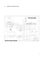
Page 14: ...14 4 SCHEMATIC WIRING DIAGRAM ...

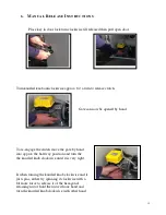
Page 15: ...d by hand To re engage the clutch move the gate by hand into approx the half way position and turn the the knurled knob clockwise until it is very tight If when turning the knurled knob clockwise and it just spins either try spinning it clockwise with a bit more force to release it of the hexagonal retaining nut or hold the nut with one hand and turn the knurled knob clockwise with other hand ...

Page 16: ...erator will not run inadvertently Gate rolls freely when in manual Gate wheels and guide rollers in good condition Gate stops in good condition and not loose Gate rack is tight correct clearances between pinion wheel rack Gate track is not damaged Gate operator mounting bolts right No oil leaks from gearboxes Gearbox mounting bolts nuts tight Inside operator and control box clean Baygon Surface Sp...

Page 17: ...ing circumstances i If no proof of date of purchase can be produced ii If the product has been used in a manner beyond its design parameters iii If the product is tampered with or repaired by personnel not authorised to do so iv In respect of loss or damage caused by rough treatment v If the product is not used and maintained in accordance with instructions or recommendations listed in this Instal...

Page 18: ......

Reviews: