6
2.
P
RODUCT
D
ESCRIPTION AND
O
PERATION
.
This operator has been developed in order to make installation, commissioning and gate operation as simple
and hassle free as possible without detracting from the quality that has always been the trademark of the GDS range of
operators.
Apart from the upgrade of inverter control to the Prostar unit and cabinet style enclosure with the option of
internal or external fixing points, the traditional limit switch type of system which initiates the ramp down time period
then stopping of the gate at the end has been changed to suit a wider range of gate sizes without having to change
chain drive sprocket sizes or limit gear ratios to match.
The chain driven cam switches are connected to initiate a second slow or homing speed which then at that
slow speed, the gate is allowed to drive into the post/mechanical stop smoothly, then after a programmed time delay,
the inverter detects a rise in current and signals the CB-6 board to stop that cycle of operation. With this method of
control, apart from the advantages over traditional limits described above, there is a more gentle or controlled stop
allowing easier aligning of electric gate contact switches, electric locks etc, and with no physical limit switches,
adjustment of the gates final stopping position will never need adjusting as long as the mechanical gate stops used are
adequate for the gate. Also, as long as the gate rack at operator drive pinion are in good order and adjusted correctly
with normal recommended maintenance, the slow down area shouldn’t need adjusting. Even if the rack does get out
of adjustment with the drive pinion, there will be a certain amount of room for error through the adequate adjustment
of the slow down area before the gate reaches the mechanical stop. Even if the gate ends up hitting the mechanical
stop at full speed either the inverter will detect the sudden current rise and cut power to the motor in turn displaying a
fault code on its display, and the clutch will slip.
The Prostar inverter has an advanced function parameter list with a detailed list of monitoring display
functions for both the operation of the inverter and status of the inputs to the inverter also with logging of the last 3
faults and recording of the operating conditions of the inverter at the first fault, taking some of the guess work out of
fault finding on site.
3.
I
NSTALLATION
D
ETAILS
Mechanical installation
•
Ensure gate rolls easily and has been installed in a manner where there is no excessive friction or binding
occurring.
•
IMPORTANT ensure there are gate stops firmly installed in the fully open and closed positions
. These stops
need to be engineered and installed such that they will be strong enough to stop the gate should the limits fail at
any time.
•
A concrete base approximately 750mm long x 300 wide x 300mm deep should be laid where the gate operator is to
be located.
•
Position operator in approximate mounting location.
•
Use a section of rack to locate the operator the correct distance away from the gate rail (finer adjustment can be
made after).
•
Dynabolt or chemical anchor the bottom mounting plate to the concrete mounting pad using 12 x 100mm fixings in
either the inside or outside slotted mounting holes.
•
Unscrew anticlockwise the manual disconnect knurled knob so the drive gear free wheels.
•
Fix the rack to the gate rail ensuring there is approximately 1mm - 2mm gap between the meshing of the teeth of
the rack and the drive gear (no more). Move the gate by hand from one end to the other while checking that the
rack is meshing correctly with the drive gear on the operator. Check also that the rack is centred around the middle
of the teeth on the drive cog – tighten the mounting plate nuts.
Summary of Contents for GDS 450 W
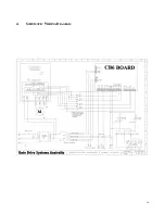
Page 14: ...14 4 SCHEMATIC WIRING DIAGRAM ...
Page 18: ......


