background image

3 | 45

Intelligent Battery

............................................................................................................................................................

20

Remote Control.....................................................................................................................................................................

24

Use of the Remote Control

..............................................................................................................................................

24

HD Image Transmission

.................................................................................................................................................

24

Installation of Mobile Device

..........................................................................................................................................

25

Control of Aircraft

..........................................................................................................................................................

25

Camera Gimbal......................................................................................................................................................................

28

Overview of Gimbal

........................................................................................................................................................

28

Installation of Camera Gimbal

.......................................................................................................................................

29

Control of Camera Gimbal

.............................................................................................................................................

29

GDU Flight App....................................................................................................................................................................

31

Device

................................................................................................................................................................................

31

Flight......................................................................................................................................................................................

37

Inspection before Flight

..................................................................................................................................................

37

Calibration of Magnetometer

.........................................................................................................................................

37

Basic Flight

.......................................................................................................................................................................

39

Technical Parameters.............................................................................................................................................................

41

Summary of Contents for SAGA

Page 1: ... 2018 GDU Tech Co Ltd All rights reserved 1 GDU SAGA User Manual V1 0 Jan 2019 ...

Page 2: ...tus Indicator 11 Flight Mode 11 Automatic Return 12 Intelligent Vision System 14 Intelligent Flight Function 16 Propeller 19 Search Keywords in a PDF document can be searched with the look up function For example for Adobe Acrobat Reader a Windows user can use Ctrl F and a Mac user can use Command F to search keywords Jump by clicking bookmark In Adobe Acrobat Reader a user can grasp the content s...

Page 3: ...n 24 Installation of Mobile Device 25 Control of Aircraft 25 Camera Gimbal 28 Overview of Gimbal 28 Installation of Camera Gimbal 29 Control of Camera Gimbal 29 GDU Flight App 31 Device 31 Flight 37 Inspection before Flight 37 Calibration of Magnetometer 37 Basic Flight 39 Technical Parameters 41 ...

Page 4: ...on Provided with HD image transmission module the aircraft can transmit HD video and take photos in real time with a transmission distance of 10km Endurance Long Lasting Performance GDU SAGA is equipped with a large capacity battery and with optimization made in terms of this dynamic system and all performance indexes its endurance time is increased to 35min Intelligent Vision System GDU SAGA is c...

Page 5: ...ill not be made if there are any updates Please refer to the latest version on the official website www gdu tech com The product parameters in the documents only represent the state as delivered and the actual situation shall remain Instructional Video In addition to documents an introductory instructional video is also available You can gain access to the instructional video on the official websi...

Page 6: ...special offers to members from time to time The user s personal information will be kept strictly confidential once the registration is completed Real Name Registration of Unmanned Aerial Vehicle UAV According to the Regulations on Real name Registration of Civil Unmanned Aerial Vehicles of the Civil Aviation Administration of China the owner of an unmanned aerial vehicle shall complete the real n...

Page 7: ... possible when the low power signal is on The aircraft will be forced to return when a severely low power signal is received at which point please control the aircraft to land in a safe place After landing please turn off the power of the aircraft prior to other actions Do not stop the motor at will during the flight under non emergency circumstances so as to protect people from being injured by a...

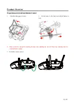
Page 8: ...ntrol 1 Unfold landing gears in turn 2 Extend arms to the limit and unfold blades in turn Please control the strength of extending the arms when unfolding the aircraft Please stop extending when the structural limit is reached 3 Unfold the remote control Click ...

Page 9: ...ED Indicator 7 Forward Vision System 2 Aircraft Front LED Indicator 8 Parameter Adjustment Interface 3 Landing Gear 9 Downward Vision System 4 Propellers 10 Gimbal Interface 5 Intelligent Battery 11 Power Button 6 Motors 12 Power Indicator of Aircraft ...

Page 10: ...10 45 Name of Remote Control Components When the gimbal of a 10X or 30X zoom camera is carried number 19 refers to the zoom thumbwheel of the camera gimbal ...

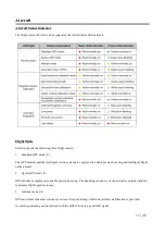
Page 11: ...m are employed to enable precise hovering and intelligent flight of the aircraft 2 Sports GPS mode F GPS module is employed to enable precise hovering The handling sensitivity of the aircraft is adjusted and the maximum flight speed increases 3 Attitude mode A GPS and visual ultrasonic system are not used for positioning while only attitude stabilization is provided Accurate positioning can be rea...

Page 12: ...vity of the aircraft will be greatly improved compared with the standard mode which means that the ordinary operation of the remote control will result in greater flight actions Sufficient flight space should be considered to ensure flight safety during the flight Automatic Return SAGA has the automatic return to home RTH function There are three ways of automatic return namely one click return lo...

Page 13: ...he App interface 2 Low power return The low power return includes three mechanisms which are the early low power warning low power return and severely low power landing Early low power warning The early low power warning will be triggered when the power of the aircraft is less than or equal to 30 At this moment the red light of the aircraft will flash slowly and the App will remind the user of the...

Page 14: ...t will in the case of encountering an obstacle ahead hover 2m away from the obstacle rise to avoid the obstacle and then return at the original height There is no obstacle avoidance under the sports mode during the return The obstacle avoidance function during return is closed by default Please start it in the settings of the App if necessary Intelligent Vision System The intelligent vision system...

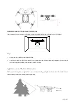
Page 15: ...ard mode 2 Turn on the power of the aircraft and wait for a successful aircraft self inspection normally the red light is on at the nose and normally the green light is on at the tail Application scenario of the forward vision system The forward vision system is applicable to an environment with good light conditions under the standard mode and an obstacle with clear texture on the flight route ...

Page 16: ... Surfaces with particularly sparse texture Surfaces with highly repetitive texture A surface with an inclination of more than 30 degrees Small obstacles e g wire mesh net for ball and twig Intelligent Flight Function Before using the intelligent flight function attention should be paid to 1 Ensure good light conditions 2 Ensure that the forward and downward vision systems cameras are clear and wit...

Page 17: ...le avoidance and radar chart display in settings perception settings The aircraft is then in the intelligent obstacle avoidance mode 2 Using the intelligent obstacle avoidance mode 1 The App displays the distance from the obstacle ahead The distance will not be displayed if it s greater than 8m as detected by the vision system The colors of the radar chart displayed on the App vary in green yellow...

Page 18: ...to stop 4 Exit the following mode and have the aircraft hover in place after clicking exit Visual Circling Operation steps 1 Click the intelligent function button and select visual circling on the pop up interface to enter the visual surrounding mode The user will be prompted to select a target 2 Select the visual circling target by double clicking or framing the target to make the aircraft fly wi...

Page 19: ...king exit the points of interest mode is exited and the aircraft will continue to hover Intelligent obstacle avoidance function is off by default Please turn it on in the App settings if required Intelligent functions are only open for partial configured aircrafts Propeller Folding propellers are used for SAGA including a propeller and b propeller which correspond to different motor rotation direc...

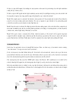
Page 20: ... the propeller blade slightly upwards and remove it after rotating by 90 degrees Finally remove the propeller Anti Ejection Propeller Design The anti ejection design mechanism of the propeller is the second safety guarantee besides the self locking design of the propeller cap Even if the propeller cap falls off the anti ejection mechanism of the propeller can also prevent the propeller blade from ...

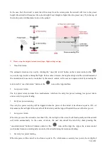
Page 21: ... the power switch once to check the battery capacity Power indicator light of intelligent battery Charge Please remove the battery from the aircraft after turning off the aircraft and connect to the specific charger to charge The charging duration of the 12000mAh battery is within4 hours ...

Page 22: ... light is green and normally on it means it is charged up if A and B are charging at the same time when A or B is not full charged it would be the red light that is normally on Charging indicator light of intelligent battery When the charger is connected with the battery please charge according to the indicated directions of the icon on the battery Do not insert upside down Removal and Installatio...

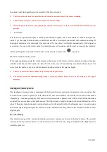
Page 23: ...emove the battery when it is turned off Remove the battery after the completing the flight Please make sure the battery cover battery is fastened with the body tightly and seamlessly Batteries use dangerous chemicals Please read the Battery Safety Guide carefully and precautions printed in the battery before use ...

Page 24: ...r of the power switch light can represent the power of remote control while the power indicator light on the remote control can represent the power of the aircraft Remote Control Charging Please charge when the remote control is off When charging the remote control it can be determined whether it is charged up by the color of the indicator light When the red light is normally on it represents that...

Page 25: ...t above the remote control 2 Press the limiter open and fix the electric equipment 3 Please connect the mobile device with the remote control through the USB port 4 When disassembling press lock and pull the device support upwards Control of Aircraft There are three operation modes supported by the remote control American Japanese and Chinese The stick controls of the three operation modes are def...

Page 26: ...rol by default is American You can change it by entering the control settings interface of the App or the remote control parameter adjustment software Switching Flight Mode The flight mode of the aircraft can be switched through flight mode via the switch on the remote control The switch is pushed to A mode attitude mode F mode GPS sports mode and P mode GPS standard mode ...

Page 27: ...de A The GPS and visual acoustic systems are not used for positioning while attitude stabilization is only provided Accurate positioning can be realized with GPS if there is a good GPS signal If there is a poor GPS signal the intelligent vision system is then used for positioning when the light conditions satisfy such a system If there is a poor GPS signal and the light conditions cannot satisfy t...

Page 28: ...mote control can control the gimbal s pitch with the angle adjustment of 90 0 Users can change perspectives quickly Please place the aircraft on a flat and broad surface before takeoff and make sure that the gimbal doesn t touch any object beforehand When the aircraft is on an uneven surface or grassland and an object touches the gimbal or the gimbal is subject to great external force the motor of...

Page 29: ...t the gimbal camera when carrying Please confirm that the cover is removed when using the aircraft It is suggested to put on the protection cover for the gimbal so as to protect the gimbal camera when the gimbal is not used Please insert and pull out the SD card after the power supply for the aircraft is disconnected Before removing the gimbal it is required to turn off the power source of the air...

Page 30: ...e by clicking the operation button C1 and C2 buttons can be user defined in the App according to your demand The camera gimbal model in the figure is only for graphic purposes According to the different configurations of the products the camera gimbals carried are different ...

Page 31: ... Media page to view photos videos etc Mine page can view flight records etc The interface and function of the App will continue to be updated It shall be subjected to the latest version Device Functions on the device page real time flight weather viewing of indexes suitable for the flight appearance display of the aircraft and connection status of the aircraft Click the preparation of picture taki...

Page 32: ... device page GPS status Display GPS satellite search number Power of aircraft Display the residual power of aircraft Connection status of aircraft Display the connection status of aircraft Flight height Display current flight height Flight distance Can take off normally ...

Page 33: ...ntrol Zoom Use the camera s zoom Switch picture taking video recording Click to switch between current picture taking video recording mode Key of picture taking video recording Display current functions picture taking video recording Camera settings Click to unfold camera function parameter settings for user defined setup One click return The aircraft makes a return voyage and lands after clicking...

Page 34: ...Map Interface Direction locking Can lock the map direction of a mobile device Switch to the map Click to change display patterns of the map between 2D and satellite maps Route planning Click to start the track planning function set the track point and upload it successfully Then the aircraft will fly to the track point in order Positioning Click to locate current location ...

Page 35: ...ettings Control setting Be able to switch the type of control custom C1 C2 key etc Flight setting Be able to set up the height limit distance limit course reversal height etc Sense setting Be able to open visual based obstacle avoidance display radar map etc Camera setting Be able to set up the resolution ratio of video picture storage capacity etc General setting Be able to set up grid effect cal...

Page 36: ... the mobile device If it is required to change the interface language please change the system language of the mobile device Presently the interface language only supports simplified Chinese and English with other language packages to be added later It shall be subject to the latest version ...

Page 37: ...etometer according to the following steps If it is required to view more information about the calibration of magnetometer please watch the relevant instructional videos 1 After starting up the remote control and the aircraft the aircraft will automatically inspect itself signified by the beeping Method 1 to calibrate the magnetometer After the beeping stops please toggle the switch flight mode of...

Page 38: ...f magnetometer is successful horizontally and the user should continue to the next step 3 Hold the aircraft by hand the nose faces downwards flashing white light at the tail turns to be white light that is normally on then the aircraft is rotated vertically and clockwise When the green light is normally on at the tail the vertical calibration of the magnetometer is successful resulting in a succes...

Page 39: ... key s and other metal objects during the calibration of magnetometer Basic Flight Select a flat and open surface turn on the power source of the aircraft and calibrate magnetometer successfully After this the indicator of the aircraft is green light Place the aircraft horizontally with the tail facing the user Takeoff Landing Takeoff Press and hold the One Click Launch button 3s on the remote con...

Page 40: ...is completed turn off the aircraft and then the remote control Before takeoff users should face the tail and over 5m away from the place where the aircraft is placed Please do not unlock and take off on a slope with a great angle ...

Page 41: ...flight time 35 minutes without wind Operating ambient temperature 10 C to 50 C Satellite positioning module GPS GLONASS dual mode Gimbal Model of gimbal that can be carried 4K 4K 30X infrared gimbal etc Controllable rotating scope Pitch 120 30 Roll 30 30 Yaw 30 30 Forward Vision System Sense range 0 5 to 15 m Operating environment The surface texture and sunlight are adequate 15 lux normal irradia...

Page 42: ...1600 Electronic shutter speed Auto Maximum resolution of pictures 4000 3000 Video resolution 4096 2160 24fps Picture format JPG Video format MP4 Storage Support Micro SD card 32G maximum Weight 249g 10X Gimbal Image sensor 1 2 3inch CMOS effective pixels 16 35 megapixels Lens FOV W 62 T 6 6 focal length 4 7 47mm ISO range 50 3200 photo 50 1600 video Electronic shutter speed auto Maximum resolution...

Page 43: ...ed detector 8 14um bad point 1 and NETD 50mK Lens FOV 39 29 focal length 20mm F1 2 electric lens Range of temperature measurement 20 50 Thermal sensitivity Ambient temperature 23 5 thermal sensitivity 0 05K when the relative aperture is 1 Accuracy of temperature measurement 2 or 2 make sure the working temperature range of the accuracy is 10 C 50 C 10m temperature adjustment when it is normal temp...

Page 44: ...tee that interference will not occur with a particular installation If this equipment does cause harmful interference to radio or television reception as can be determined by turning the equipment in question off and on the user is encouraged to try to correct the interference by one or more of the following measures Reorient or relocate the receiving antenna Increase the separation between the eq...

Page 45: ...radio frequency exposure compliance This transmitter must not be co located or operating in conjunction with any other antenna or transmitter GDU Remote controller The portable device is designed to meet the requirements for exposure to radio waves as established by the Federal Communications Commission USA These requirements set an SAR limit of 1 6 W averaged over one gram of tissue The highest S...

Reviews: