GE Multilin
L30 Line Current Differential System
5-75
5 SETTINGS
5.4 SYSTEM SETUP
5
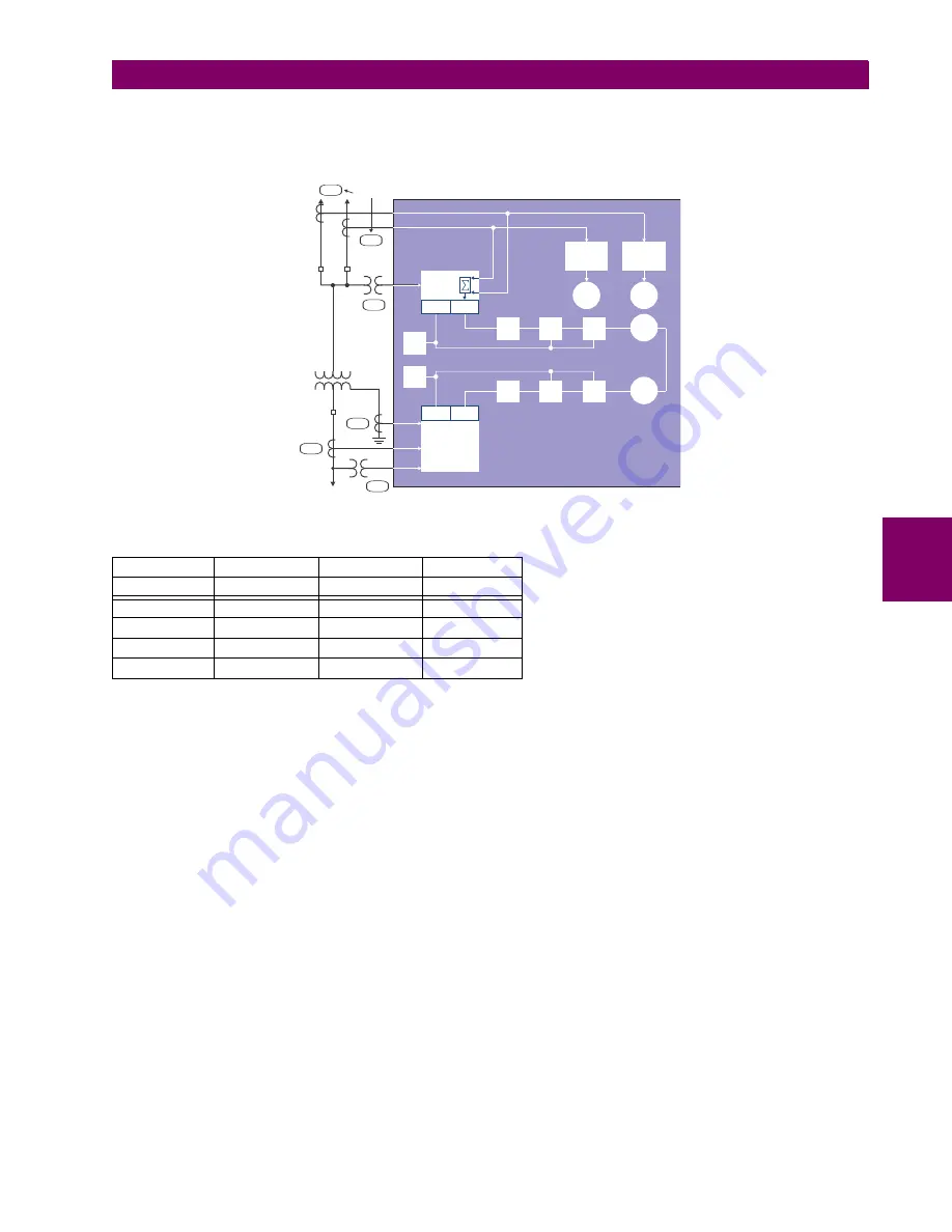
This configuration could be used on a two-winding transformer, with one winding connected into a breaker-and-a-half sys-
tem. The following figure shows the arrangement of sources used to provide the functions required in this application, and
the CT/VT inputs that are used to provide the data.
Figure 5–17: EXAMPLE USE OF SOURCES
Y LV
D HV
AUX
SRC 1
SRC 2
SRC 3
Phase CT
M1
F1+F5
None
Ground CT
M1
None
None
Phase VT
M5
None
None
Aux VT
None
None
U1
F 5
F 1
DSP Bank
U 1
M 1
M 1
M 5
51BF-1
51BF-2
Source 4
87T
51P
UR Relay
A
V
V
A
W
W
Var
Var
Amps
Source 1
Source 3
Volts
Amps
Amps
Volts
Amps
Source 2
Summary of Contents for L30
Page 10: ...x L30 Line Current Differential System GE Multilin TABLE OF CONTENTS ...
Page 30: ...1 20 L30 Line Current Differential System GE Multilin 1 5 USING THE RELAY 1 GETTING STARTED 1 ...
Page 370: ...5 244 L30 Line Current Differential System GE Multilin 5 10 TESTING 5 SETTINGS 5 ...
Page 464: ...A 10 L30 Line Current Differential System GE Multilin A 1 PARAMETER LISTS APPENDIX A A ...
Page 600: ...C 30 L30 Line Current Differential System GE Multilin C 7 LOGICAL NODES APPENDIX C C ...
Page 610: ...D 10 L30 Line Current Differential System GE Multilin D 1 IEC 60870 5 104 APPENDIX D D ...
Page 622: ...E 12 L30 Line Current Differential System GE Multilin E 2 DNP POINT LISTS APPENDIX E E ...
Page 634: ...F 12 L30 Line Current Differential System GE Multilin F 3 WARRANTY APPENDIX F F ...
Page 644: ...x L30 Line Current Differential System GE Multilin INDEX ...


