GE Multilin
L30 Line Current Differential System
5-211
5 SETTINGS
5.7 CONTROL ELEMENTS
5
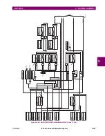
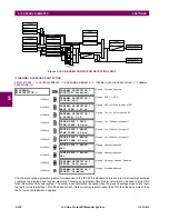
Figure 5–103: BREAKER ARCING CURRENT SCHEME LOGIC
SETTING
SETTING
SETTINGS
SETTING
COMMAND
ACTUAL VALUE
FLEXLOGIC OPERANDS
SETTING
BREAKER 1 ARCING
AMP FUNCTION:
BREAKER 1 ARCING
AMP BLOCK:
BREAKER 1 ARCING
AMP INIT-A:
BREAKER 1 ARCING
AMP INIT-B:
BREAKER 1 ARCING
AMP INIT-C:
BREAKER 1 ARCING
AMP LIMIT:
CLEAR BREAKER 1
ARCING AMPS:
BKR 1 ARCING AMP A
Φ
BKR 1 OPERATING TIME A
Φ
BKR 1 OPERATING TIME B
Φ
BKR 1 OPERATING TIME C
Φ
BKR 1 OPERATING TIME
BKR 1 ARCING AMP B
Φ
BKR 1 ARCING AMP C
Φ
BKR1 ARC OP
BKR1 ARC DPO
BREAKER 1 ARCING
AMP SOURCE:
I
A
I
B
I
C
Off=0
Off=0
Off=0
Off=0
NO=0
YES=1
Enabled=1
Disabled=0
AND
AND
AND
AND
AND
OR
OR
827071A3.CDR
KA Cycle Limit
2
*
SETTING
BREAKER 1 ARCING
AMP DELAY:
100 ms
0
0
Set All To Zero
Add to
Accumulator
Integrate
Integrate
Integrate
Select
Highest
Value
RUN
RUN
RUN
I
B -Cycle
I
A -Cycle
I
C -Cycle
2
2
2
Summary of Contents for L30
Page 10: ...x L30 Line Current Differential System GE Multilin TABLE OF CONTENTS ...
Page 30: ...1 20 L30 Line Current Differential System GE Multilin 1 5 USING THE RELAY 1 GETTING STARTED 1 ...
Page 370: ...5 244 L30 Line Current Differential System GE Multilin 5 10 TESTING 5 SETTINGS 5 ...
Page 464: ...A 10 L30 Line Current Differential System GE Multilin A 1 PARAMETER LISTS APPENDIX A A ...
Page 600: ...C 30 L30 Line Current Differential System GE Multilin C 7 LOGICAL NODES APPENDIX C C ...
Page 610: ...D 10 L30 Line Current Differential System GE Multilin D 1 IEC 60870 5 104 APPENDIX D D ...
Page 622: ...E 12 L30 Line Current Differential System GE Multilin E 2 DNP POINT LISTS APPENDIX E E ...
Page 634: ...F 12 L30 Line Current Differential System GE Multilin F 3 WARRANTY APPENDIX F F ...
Page 644: ...x L30 Line Current Differential System GE Multilin INDEX ...


