2-16
L30 Line Current Differential System
GE Multilin
2.3 FUNCTIONALITY
2 PRODUCT DESCRIPTION
2
sors communicate their results to each other so that if any failures are detected, they can be reported to the user. Each
processor must successfully complete its self tests before the relay begins protection activities.
During both startup and normal operation, the CPU polls all plug-in modules and checks that every one answers the
poll. The CPU compares the module types that identify themselves to the relay order code stored in memory and
declares an alarm if a module is either non-responding or the wrong type for the specific slot. When running under nor-
mal power system conditions, the relay processors will have idle time. During this time, each processor performs back-
ground self-tests that are not disruptive to the foreground processing.
2.3.3 OTHER FUNCTIONS
a) ALARMS
The relay contains a dedicated alarm relay, the critical failure alarm, housed in the power supply module. This output relay
is not user programmable. This relay has form-C contacts and is energized under normal operating conditions. The critical
failure alarm will become de-energized if the relay self test algorithms detect a failure that would prevent the relay from
properly protecting the transmission line.
b) LOCAL USER INTERFACE
The local user interface (on the faceplate) consists of a 2
20 liquid crystal display (LCD) and keypad. The keypad and dis-
play may be used to view data from the relay, to change settings in the relay, or to perform control actions. Also, the face-
plate provides LED indications of status and events.
c) TIME SYNCHRONIZATION
The relay includes a clock which can run freely from the internal oscillator or be synchronized from an external IRIG-B sig-
nal. With the external signal, all relays wired to the same synchronizing signal will be synchronized to within 0.1 millisecond.
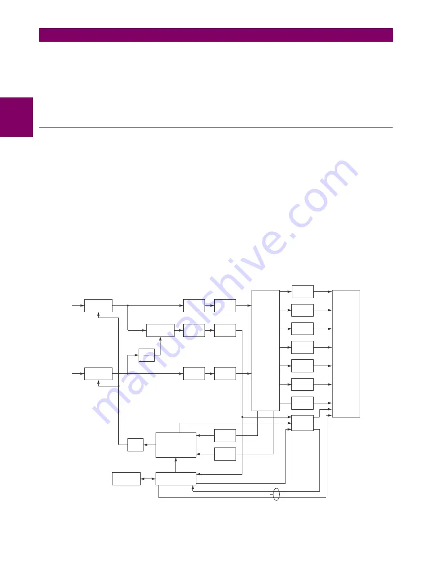
d) FUNCTION DIAGRAMS
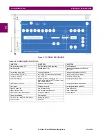
Figure 2–3: L30 BLOCK DIAGRAM
831732A3.CDR
I
V
Sample Raw
Value
Sample Raw
Value
Sample
Hold
Master
Clock
Remote Relay
Communications
Interface
Phase and Frequency
Locked Loop (PFLL)
Phase
Deviation
Frequency
Deviation
Charging Current
Comp.
Offset
Removal
Offset
Removal
Filter
PFLL Status
Compute
Phaselets
Compute
Phaselets
Compute
Phaselets
UR Platform
Phasors
Computations
Disturbance
Detector
67P&N
50P,N&G
51P,N&G
27P
59P
87L
Algorithm
21P&G
Trip Output
Configurable
Logic
Direct Transfer Trip
PHASELETS TO REMOTE
PHASELETS FROM REMOTE
dV
dt
Summary of Contents for L30
Page 10: ...x L30 Line Current Differential System GE Multilin TABLE OF CONTENTS ...
Page 30: ...1 20 L30 Line Current Differential System GE Multilin 1 5 USING THE RELAY 1 GETTING STARTED 1 ...
Page 370: ...5 244 L30 Line Current Differential System GE Multilin 5 10 TESTING 5 SETTINGS 5 ...
Page 464: ...A 10 L30 Line Current Differential System GE Multilin A 1 PARAMETER LISTS APPENDIX A A ...
Page 600: ...C 30 L30 Line Current Differential System GE Multilin C 7 LOGICAL NODES APPENDIX C C ...
Page 610: ...D 10 L30 Line Current Differential System GE Multilin D 1 IEC 60870 5 104 APPENDIX D D ...
Page 622: ...E 12 L30 Line Current Differential System GE Multilin E 2 DNP POINT LISTS APPENDIX E E ...
Page 634: ...F 12 L30 Line Current Differential System GE Multilin F 3 WARRANTY APPENDIX F F ...
Page 644: ...x L30 Line Current Differential System GE Multilin INDEX ...

