5-78
L30 Line Current Differential System
GE Multilin
5.4 SYSTEM SETUP
5 SETTINGS
5
•
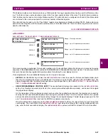
ZERO-SEQUENCE CURRENT REMOVAL:
This setting facilitates application of the L30 to transmission lines with one
or more tapped transformers without current measurement at the taps. If the tapped transformer is connected in a
grounded wye on the line side, it becomes a source of the zero-sequence current for external ground faults. As the
transformer current is not measured by the L30 protection system, the zero-sequence current would create a spurious
differential signal and may cause a false trip.
If enabled, this setting forces the L30 to remove zero-sequence current from the phase currents prior to forming their
differential signals, ensuring protection stability on external ground faults. However, zero-sequence current removal
may cause all three phases to trip for internal ground faults. Consequently, a phase selective operation of the L30 is
not retained if the setting is enabled. This does not impose any limitation, as single-pole tripping is not recommended
for lines with tapped transformers. Refer to chapter 9 for guidelines.
•
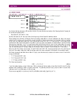
LOCAL (TERMINAL 1 and TERMINAL 2) ID NUMBER:
In installations using multiplexers or modems for communica-
tion, it is desirable to ensure the data used by the relays protecting a given line comes from the correct relays. The L30
performs this check by reading the ID number contained in the messages sent by transmitting relays and comparing
this ID to the programmed correct ID numbers by the receiving relays. This check is used to block the differential ele-
ment of a relay, if the channel is inadvertently set to loopback mode, by recognizing its own ID on a received channel.
If an incorrect ID is found on a either channel during normal operation, the FlexLogic™ operand
87 CH1(2) ID FAIL
is
set, driving the event with the same name. The result of channel identification is also available in
ACTUAL VALUES
STATUS
CHANNEL TESTS
VALIDITY OF CHANNEL CONFIGURATION
for commissioning purposes. The default value
“0” at local relay ID setting indicates that the channel ID number is not to be checked. Refer to the
Current differential
section in this chapter for additional information.
For two-terminal applications, only the
LOCAL ID NUMBER
and
TERMINAL 1 ID NUMBER
should be used. The
TERMINAL 2
ID NUMBER
is used for three-terminal applications.
•
CHNL ASYM COMP:
This setting enables/disables channel asymmetry compensation. The compensation is based on
absolute time referencing provided by GPS-based clocks via the Precision Time Protocol or IRIG-B. Use this feature
on multiplexed channels where channel asymmetry can be expected and which otherwise causes errors in current dif-
ferential calculations. The feature takes effect if all terminals are provided with reliable GPS clock signals. If the GPS
clock signal is lost at any terminal of the current differential protection system, or the real time clock not configured,
then the compensation is not calculated. If the compensation is in place prior to losing the GPS time reference, the last
(memorized) correction is applied as long as the value of
CHNL ASYM COMP
is “On”. See chapter 9 for additional infor-
mation.
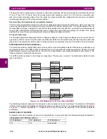
The GPS-based compensation for channel asymmetry can take three different effects:
•
If the
CHNL ASYM COMP
selected FlexLogic operand is “Off”, compensation is not applied and the L30 uses only
the ping-pong technique.
•
If the
CHNL ASYM COMP
selected FlexLogic operand is “On” and all terminals have a valid time reference, then
compensation is applied and the L30 effectively uses GPS time referencing tracking channel asymmetry if the lat-
ter fluctuates.
•
If
CHNL ASYM COMP
is “On” and not all terminals have a valid time reference, then compensation is not applied (if
the system was not compensated prior to the problem), or the memorized (last valid) compensation is used if com-
pensation was in effect prior to the problem.
A terminal is considered to have a valid time reference while the BLOCK GPS TIME REF selected FlexLogic operand
is Off and the LOCAL GPS TROUBLE signal is Off. The LOCAL GPS TROUBLE signal is On if the real time clock is
not locked to global time via PP, PTP, or IRIG-B. It is also On if locked via Amplitude Modulated IRIG-B, and if locked
via PP or PTP and indicated clock accuracy is less than 250 µs.
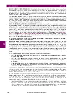
The
CHNL ASYM COMP
setting dynamically turns the GPS compensation on and off. A FlexLogic operand that combines
several factors is typically used. The L30 protection system does not incorporate any pre-defined way of treating cer-
tain conditions, such as failure of the GPS receiver, loss of satellite signal, channel asymmetry prior to the loss of refer-
ence time, or change of the round trip time prior to loss of the time reference. Virtually any philosophy can be
programmed by selecting the
CHNL ASYM COMP
setting. Factors to consider are:
•
Fail-safe output of the GPS receiver
. Some receivers may be equipped with the fail-safe output relay. The L30 sys-
tem requires a maximum error of 250
s. The fail-safe output of the GPS receiver may be connected to the local
L30 via an input contact. In the case of GPS receiver fail, the channel compensation function can be effectively
disabled by using the input contact in conjunction with the
BLOCK GPS TIME REF
(GPS) setting.
Summary of Contents for L30
Page 10: ...x L30 Line Current Differential System GE Multilin TABLE OF CONTENTS ...
Page 30: ...1 20 L30 Line Current Differential System GE Multilin 1 5 USING THE RELAY 1 GETTING STARTED 1 ...
Page 370: ...5 244 L30 Line Current Differential System GE Multilin 5 10 TESTING 5 SETTINGS 5 ...
Page 464: ...A 10 L30 Line Current Differential System GE Multilin A 1 PARAMETER LISTS APPENDIX A A ...
Page 600: ...C 30 L30 Line Current Differential System GE Multilin C 7 LOGICAL NODES APPENDIX C C ...
Page 610: ...D 10 L30 Line Current Differential System GE Multilin D 1 IEC 60870 5 104 APPENDIX D D ...
Page 622: ...E 12 L30 Line Current Differential System GE Multilin E 2 DNP POINT LISTS APPENDIX E E ...
Page 634: ...F 12 L30 Line Current Differential System GE Multilin F 3 WARRANTY APPENDIX F F ...
Page 644: ...x L30 Line Current Differential System GE Multilin INDEX ...


