GE Multilin
L30 Line Current Differential System
5-103
5 SETTINGS
5.4 SYSTEM SETUP
5
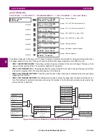
C37.118 PMU 1 CONFIGURATION
PATH: SETTINGS
SYSTEM SETUP
PHASOR MEASUREMENT
BASIC CONFIGURATION
PMU 1
PMU 1 BASIC CONFIGU-
RATION
37.118 PMU 1 CONFIGURATION
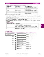
IEC 61850–90–5 PMU 1 CONFIGURATION
PATH: SETTINGS
SYSTEM SETUP
PHASOR MEASUREMENT
BASIC CONFIGURATION
PMU1
PMU 1 BASIC CONFIGURA-
TION
90 – 5 PMU 1 CONFIGURATION
This section contains basic phasor measurement unit (PMU) data, such as functions, source settings, and names.
•
PMU 1 FUNCTION
: This setting enables the LOGICAL Device PMU 1 functionality. Use this setting to permanently
enable or disable the feature.
•
PMU 1 IDCODE
: This setting assigns a numerical ID to the PMU. It corresponds to the IDCODE field of the data, con-
figuration, header, and command frames of the C37.118 protocol. The PMU uses this value when sending data, config-
uration, and header frames; and it responds to this value when receiving the command frame. This is used when only
data from one PMU is present.
•
PMU 1 STN
: This setting assigns an alphanumeric ID to the PMU station. It corresponds to the STN field of the config-
uration frame of the C37.118 protocol. This value is a 16-character ASCII string as per the C37.118 standard.
•
PMU 1 SIGNAL SOURCE
: This setting specifies one of the available L30 signal sources for processing in the PMU.
Note that any combination of voltages and currents can be configured as a source. The current channels could be con-
figured as sums of physically connected currents. This facilitates PMU applications in breaker-and-a-half, ring-bus, and
similar arrangements. The PMU feature calculates voltage phasors for actual voltage (A, B, C, and auxiliary) and cur-
rent (A, B, C, and ground) channels of the source, as well as symmetrical components (0, 1, and 2) of both voltages
and currents. When configuring communication and recording features of the PMU, the user could select – from the
above superset – the content to be sent out or recorded. When one source is selected by one PMU, it cannot be
selected by another PMU.
•
PMU 1 CLASS (Range P, M, None)
: This setting selects the synchrophasor class. Note that a reporting rate of 100 or
120 can only be selected for class P synchrophasors and if the system frequency is 50 Hz or 60 Hz, respectively.
•
PMU 1 NETWORK REPORTING FORMAT
: This setting selects whether synchrophasors are reported as 16-bit inte-
gers or 32-bit IEEE floating point numbers. This setting complies with bit-1 of the FORMAT field of the C37.118 config-
uration frame. Note that this setting applies to synchrophasors only; the user-selectable FlexAnalog™ channels are
always transmitted as 16-bit integer values.
•
PMU 1 NETWORK REPORTING STYLE
: This setting selects whether synchrophasors are reported in rectangular
(real and imaginary) coordinates or in polar (magnitude and angle) coordinates. This setting complies with bit-0 of the
FORMAT field of the C37.118 configuration frame.
•
PMU 1 REPORTING RATE
: This setting specifies the reporting rate for the network (Ethernet) port. This value applies
to all PMU streams of the device that are assigned to transmit over this aggregator. For a system frequency of 60 Hz
MESSAGE
PMU 1 D-CH-16:
Off
Range: FlexLogic operand
Default: Off
MESSAGE
PMU 1 REC D-CH-16
NAME: DigChannel16
Range: 16-character ASCII string
Default: DigChannel16
MESSAGE
PMU 1 REC D-CH-16
NORMAL STATE: Off
Range: Off, On
Default: Off
37.118 PMU 1
CONFIGURATION
PMU 1 FORMAT:
Integer
Range: Integer, Floating-point
Default: Integer
MESSAGE
PMU 1 STYLE:
Polar
Range: Polar, Rectangular
Default: Polar
90–5 PMU 1
CONFIGURATION
PMU 1 LDNAME
Range: 65 char ASCII text
Default: blank
Summary of Contents for L30
Page 10: ...x L30 Line Current Differential System GE Multilin TABLE OF CONTENTS ...
Page 30: ...1 20 L30 Line Current Differential System GE Multilin 1 5 USING THE RELAY 1 GETTING STARTED 1 ...
Page 370: ...5 244 L30 Line Current Differential System GE Multilin 5 10 TESTING 5 SETTINGS 5 ...
Page 464: ...A 10 L30 Line Current Differential System GE Multilin A 1 PARAMETER LISTS APPENDIX A A ...
Page 600: ...C 30 L30 Line Current Differential System GE Multilin C 7 LOGICAL NODES APPENDIX C C ...
Page 610: ...D 10 L30 Line Current Differential System GE Multilin D 1 IEC 60870 5 104 APPENDIX D D ...
Page 622: ...E 12 L30 Line Current Differential System GE Multilin E 2 DNP POINT LISTS APPENDIX E E ...
Page 634: ...F 12 L30 Line Current Differential System GE Multilin F 3 WARRANTY APPENDIX F F ...
Page 644: ...x L30 Line Current Differential System GE Multilin INDEX ...

