GE Multilin
L30 Line Current Differential System
5-177
5 SETTINGS
5.6 GROUPED ELEMENTS
5
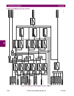
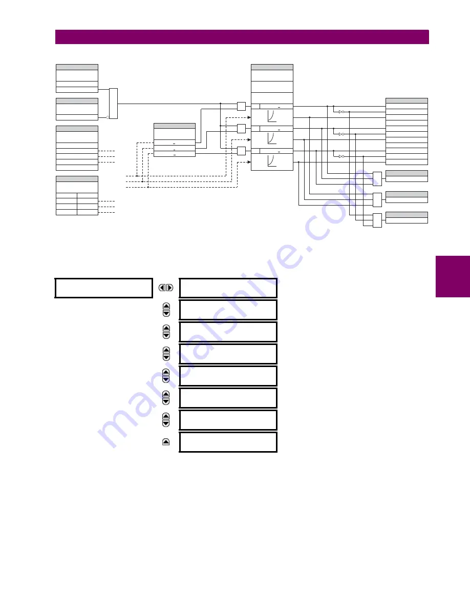
Figure 5–81: PHASE UNDERVOLTAGE1 SCHEME LOGIC
c) PHASE OVERVOLTAGE
(ANSI 59P, IEC PTOV)
PATH: SETTINGS
GROUPED ELEMENTS
SETTING GROUP 1(6)
VOLTAGE ELEMENTS
PHASE OVERVOLTAGE1
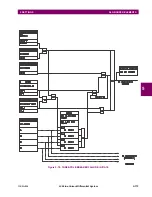
The phase overvoltage element may be used as an instantaneous element with no intentional time delay or as a definite
time element. The input voltage is the phase-to-phase voltage, either measured directly from delta-connected VTs or as cal-
culated from phase-to-ground (wye) connected VTs. The specific voltages to be used for each phase are shown below.
PHASE
OVERVOLTAGE1
PHASE OV1
FUNCTION: Disabled
Range: Disabled, Enabled
MESSAGE
PHASE OV1 SIGNAL
SOURCE: SRC 1
Range: SRC 1, SRC 2
MESSAGE
PHASE OV1
PICKUP: 1.000 pu
Range: 0.000 to 3.000 pu in steps of 0.001
MESSAGE
PHASE OV1 PICKUP
DELAY: 1.00
s
Range: 0.00 to 600.00 s in steps of 0.01
MESSAGE
PHASE OV1 RESET
DELAY: 1.00
s
Range: 0.00 to 600.00 s in steps of 0.01
MESSAGE
PHASE OV1 BLOCK:
Off
Range: FlexLogic Operand
MESSAGE
PHASE OV1
TARGET: Self-reset
Range: Self-reset, Latched, Disabled
MESSAGE
PHASE OV1
EVENTS: Disabled
Range: Disabled, Enabled
PHASE UV1
FUNCTION:
PHASE UV1
BLOCK:
PHASE UV1 SOURCE:
PHASE UV1 MODE:
PHASE UV1
PICKUP:
PHASE UV1
CURVE:
PHASE UV1
DELAY:
PHASE UV1
MINIMUM VOLTAGE:
Disabled = 0
Off = 0
Source VT = Delta
Phase to Ground Phase to Phase
RUN
RUN
VCG or VCA PICKUP
VBG or VBC PICKUP
VAG or VAB Minimum
VBG or VBC Minimum
VCG or VCA Minimum
Source VT = Wye
VAG
VAB
VBG
VBC
VCG
VCA
Enabled = 1
VAB
VBC
VCA
PHASE UV1 A PKP
PHASE UV1 B PKP
PHASE UV1 C PKP
PHASE UV1 PKP
PHASE UV1 A DPO
PHASE UV1 B DPO
PHASE UV1 C DPO
PHASE UV1 A OP
PHASE UV1 B OP
PHASE UV1 C OP
PHASE UV1 OP
AND
SETTING
SETTING
SETTING
SETTING
SETTING
SETTING
FLEXLOGIC OPERANDS
FLEXLOGIC OPERAND
FLEXLOGIC OPERAND
827039AB.CDR
AND
AND
AND
OR
OR
<
<
<
<
<
}
t
V
t
t
V
V
VAG or VAB PICKUP
<
RUN
PHASE UV1 DPO
FLEXLOGIC OPERAND
AND
Summary of Contents for L30
Page 10: ...x L30 Line Current Differential System GE Multilin TABLE OF CONTENTS ...
Page 30: ...1 20 L30 Line Current Differential System GE Multilin 1 5 USING THE RELAY 1 GETTING STARTED 1 ...
Page 370: ...5 244 L30 Line Current Differential System GE Multilin 5 10 TESTING 5 SETTINGS 5 ...
Page 464: ...A 10 L30 Line Current Differential System GE Multilin A 1 PARAMETER LISTS APPENDIX A A ...
Page 600: ...C 30 L30 Line Current Differential System GE Multilin C 7 LOGICAL NODES APPENDIX C C ...
Page 610: ...D 10 L30 Line Current Differential System GE Multilin D 1 IEC 60870 5 104 APPENDIX D D ...
Page 622: ...E 12 L30 Line Current Differential System GE Multilin E 2 DNP POINT LISTS APPENDIX E E ...
Page 634: ...F 12 L30 Line Current Differential System GE Multilin F 3 WARRANTY APPENDIX F F ...
Page 644: ...x L30 Line Current Differential System GE Multilin INDEX ...


