G
E
M
u
l t i l i n
L30 Line Current Differential System
5-199
5 SETTINGS
5.7 CONTROL ELEMENTS
5
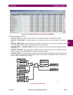
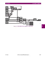
The maximum number of autoreclosure elements available is equal to the number of installed CT banks.
The autoreclosure feature is intended for use with transmission and distribution lines, in three-pole tripping schemes for sin-
gle breaker applications. Up to four selectable reclosures ‘shots’ are possible prior to locking out. Each shot has an inde-
pendently settable dead time. The protection settings can be changed between shots if so desired, using FlexLogic™.
Logic inputs are available for disabling or blocking the scheme.
Faceplate panel LEDs indicate the state of the autoreclose scheme as follows:
•
Reclose Enabled: The scheme is enabled and may reclose if initiated.
•
Reclose Disabled: The scheme is disabled.
•
Reclose In Progress: An autoreclosure has been initiated but the breaker has not yet been signaled to close.
•
Reclose Locked Out: The scheme has generated the maximum number of breaker closures allowed and, as the fault
persists, will not close the breaker again; known as ‘Lockout’. The scheme may also be sent in ‘Lockout’ when the
incomplete sequence timer times out or when a block signal occurs while in ‘reclose in progress’. The scheme must be
reset from Lockout in order to perform reclose for further faults.
The reclosure scheme is considered
enabled
when all of the following conditions are true:
•
The
AR1 FUNCTION
is set to “Enabled”.
•
The scheme is not in the ‘Lockout’ state.
•
The ‘Block’ input is not asserted.
•
The
AR1 BLK TIME UPON MNL CLS
timer is not active.
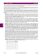
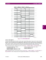
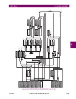
The autoreclose scheme is initiated by a trip signal from any selected protection feature operand. The scheme is initiated
provided the circuit breaker is in the closed state before protection operation.
The reclose-in-progress (RIP) is set when a reclosing cycle begins following a reclose initiate signal. Once the cycle is suc-
cessfully initiated, the RIP signal will seal-in and the scheme will continue through its sequence until one of the following
conditions is satisfied:
•
The close signal is issued when the dead timer times out, or
•
The scheme goes to lockout.
While RIP is active, the scheme checks that the breaker is open and the shot number is below the limit, and then begins
measuring the dead time.
Each of the four possible shots has an independently settable dead time. Two additional timers can be used to increase the
initial set dead times 1 to 4 by a delay equal to
AR1 DELAY 1
or
AR1 DELAY 2
or the sum of these two delays depending on the
selected settings. This offers enhanced setting flexibility using FlexLogic™ operands to turn the two additional timers “on”
and “off”. These operands may possibly include
AR1 SHOT CNT =n
,
SETTING GROUP ACT 1
, etc. The autoreclose provides
up to maximum 4 selectable shots. Maximum number of shots can be dynamically modified through the settings
AR1
REDUCE MAX TO 1 (2, 3)
, using the appropriate FlexLogic™ operand.
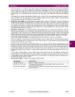
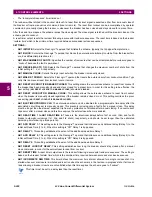
Scheme lockout blocks all phases of the reclosing cycle, preventing automatic reclosure, if any of the following occurs:
•
The maximum shot number was reached.
•
A ‘Block’ input is in effect (for instance; Breaker Failure, bus differential protection operated, etc.).
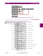
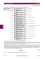
MESSAGE
AR1 DELAY 2:
0.000 s
Range: 0.00 to 655.35 s in steps of 0.01
MESSAGE
AR1 RESET LOCKOUT
DELAY: 60.000
Range: 0.00 to 655.35 s in steps of 0.01
MESSAGE
AR1 RESET TIME:
60.000 s
Range: 0.00 to 655.35 s in steps of 0.01
MESSAGE
AR1 INCOMPLETE SEQ
TIME: 5.000
s
Range: 0.00 to 655.35 s in steps of 0.01
MESSAGE
AR1 EVENTS:
Disabled
Range: Disabled, Enabled
Summary of Contents for L30
Page 10: ...x L30 Line Current Differential System GE Multilin TABLE OF CONTENTS ...
Page 30: ...1 20 L30 Line Current Differential System GE Multilin 1 5 USING THE RELAY 1 GETTING STARTED 1 ...
Page 370: ...5 244 L30 Line Current Differential System GE Multilin 5 10 TESTING 5 SETTINGS 5 ...
Page 464: ...A 10 L30 Line Current Differential System GE Multilin A 1 PARAMETER LISTS APPENDIX A A ...
Page 600: ...C 30 L30 Line Current Differential System GE Multilin C 7 LOGICAL NODES APPENDIX C C ...
Page 610: ...D 10 L30 Line Current Differential System GE Multilin D 1 IEC 60870 5 104 APPENDIX D D ...
Page 622: ...E 12 L30 Line Current Differential System GE Multilin E 2 DNP POINT LISTS APPENDIX E E ...
Page 634: ...F 12 L30 Line Current Differential System GE Multilin F 3 WARRANTY APPENDIX F F ...
Page 644: ...x L30 Line Current Differential System GE Multilin INDEX ...

