5-216
L30 Line Current Differential System
GE Multilin
5.7 CONTROL ELEMENTS
5 SETTINGS
5
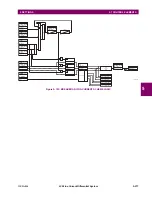
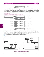
Figure 5–106: BROKEN CONDUCTOR DETECTION LOGIC
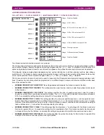
f) THERMAL OVERLOAD PROTECTION
PATH: SETTINGS
CONTROL ELEMENTS
MONITORING ELEMENTS
THERMAL OVERLOAD PROTECTION
THERMAL
PROTECTION 1(2)
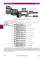
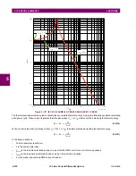
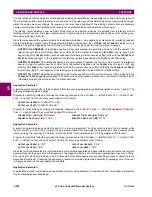
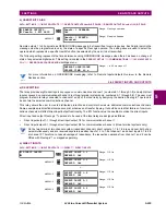
The thermal overload protection element corresponds to the IEC 255-8 standard and is used to detect thermal overload
conditions in protected power system elements. Choosing an appropriate time constant element can be used to protect dif-
ferent elements of the power system. The cold curve characteristic is applied when the previous averaged load current over
the last 5 cycles is less than 10% of the base current. If this current is greater or equal than 10% than the base current, then
the hot curve characteristic is applied.
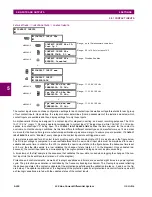
THERMAL
PROTECTION 1
THERMAL PROTECTION 1
FUNCTION: Disabled
Range: Disabled, Enabled
MESSAGE
THERMAL PROTECTION 1
SOURCE: SRC1
Range: SRC 1, SRC 2
MESSAGE
THERMAL PROTECTION 1
BASE CURR: 0.80 pu
Range: 0.20 to 3.00 pu in steps of 0.01
MESSAGE
THERMAL PROTECTION 1
k FACTOR: 1.10
Range: 1.00 to 1.20 in steps of 0.05
MESSAGE
THERM PROT 1 TRIP
TIME CONST: 45 min.
Range: 0 to 1000 min. in steps of 1
MESSAGE
THERM PROT 1 RESET
TIME CONST: 45 min.
Range: 0 to 1000 min. in steps of 1
MESSAGE
THERM PROT 1 MINIM
RESET TIME: 20 min.
Range: 0 to 1000 min. in steps of 1
MESSAGE
THERM PROT 1 RESET:
Off
Range: FlexLogic operand
MESSAGE
THERM PROT 1 BLOCK:
Off
Range: FlexLogic operand
MESSAGE
THERMAL PROTECTION 1
TARGET: Self-reset
Range: Self-reset, Latched, Disabled
MESSAGE
THERMAL PROTECTION 1
EVENTS: Disabled
Range: Disabled, Enabled
SETTINGS
BROKEN CONDUCTOR 1
FUNCTION:
Enabled = 1
AN
D
BROKEN CONDCT 1 BLK:
Off = 0
SETTINGS
BROKEN CONDUCTOR 1
SOURCE:
I2
FLEXLOGIC OPERAND
BROKEN CONDUCT 1
OP
I1
Ia
Ib
Ic
AN
D
SETTING
BROKEN CONDUCTOR 1
I1 MIN :
| I1 | > I1 MIN
| Ia | < I1 MIN
| Ib | < I1 MIN
| Ic | < I1 MIN
| Ia’ | - | Ia | > 0.05pu
| Ib’ | - | Ib | > 0.05pu
| Ic’ | - | Ic | > 0.05pu
Where I’ is 4 cycles old
AN
D
AND
OR
One phase current loss
detection
RUN
2 cyc
0
AN
D
OR
SETTING
BROKEN CONDUCTOR 1
I1 MAX :
RUN
| I1 | < I1 MAX
| I2 | / | I1 |> RATIO
BROKEN CONDUCTOR 1
I2/I1 RATIO :
t
PKP
0
SETTING
BROKEN CONDUCTOR 1
I1 MAX :
FLEXLOGIC OPERAND
BROKEN CONDUCT 1
PKP
Summary of Contents for L30
Page 10: ...x L30 Line Current Differential System GE Multilin TABLE OF CONTENTS ...
Page 30: ...1 20 L30 Line Current Differential System GE Multilin 1 5 USING THE RELAY 1 GETTING STARTED 1 ...
Page 370: ...5 244 L30 Line Current Differential System GE Multilin 5 10 TESTING 5 SETTINGS 5 ...
Page 464: ...A 10 L30 Line Current Differential System GE Multilin A 1 PARAMETER LISTS APPENDIX A A ...
Page 600: ...C 30 L30 Line Current Differential System GE Multilin C 7 LOGICAL NODES APPENDIX C C ...
Page 610: ...D 10 L30 Line Current Differential System GE Multilin D 1 IEC 60870 5 104 APPENDIX D D ...
Page 622: ...E 12 L30 Line Current Differential System GE Multilin E 2 DNP POINT LISTS APPENDIX E E ...
Page 634: ...F 12 L30 Line Current Differential System GE Multilin F 3 WARRANTY APPENDIX F F ...
Page 644: ...x L30 Line Current Differential System GE Multilin INDEX ...


