GE Multilin
L30 Line Current Differential System
5-229
5 SETTINGS
5.8 INPUTS AND OUTPUTS
5
b) USERST BIT PAIRS
PATH: SETTINGS
INPUTS/OUTPUTS
REMOTE OUTPUTS UserSt BIT PAIRS
REMOTE OUTPUTS UserSt- 1(32) BIT PAIR
Remote outputs 1 to 32 originate as GSSE/GOOSE messages to be transmitted to remote devices. Each digital point in the
message must be programmed to carry the state of a specific FlexLogic operand. The setting above is used to select the
operand which represents a specific UserSt function (as selected by the user) to be transmitted.
The following setting represents the time between sending GSSE/GOOSE messages when there has been no change of
state of any selected digital point. This setting is located in the
PRODUCT SETUP
COMMUNICATIONS
IEC 61850 PROTO-
COL
GSSE/GOOSE CONFIGURATION
settings menu.
For more information on GSSE/GOOSE messaging, refer to Remote Inputs/Outputs Overview in the Remote
Devices section.
5.8.9 DIRECT INPUTS AND OUTPUTS
a) DESCRIPTION
The relay provides eight direct inputs conveyed on communications channel 1 (numbered 1-1 through 1-8) and eight direct
inputs conveyed on communications channel 2 (on three-terminal systems only, numbered 2-1 through 2-8). The user must
program the remote relay connected to channels 1 and 2 of the local relay by assigning the desired FlexLogic™ operand to
be sent via the selected communications channel.
This relay allows the user to create distributed protection and control schemes via dedicated communications channels.
Some examples are directional comparison pilot schemes and transfer tripping. It should be noted that failures of communi-
cations channels will affect direct input/output functionality. The 87L function must be enabled to utilize the direct inputs.
Direct input and output FlexLogic™ operands to be used at the local relay are assigned as follows:
•
Direct input/output 1-1 through direct input/output 1-8 for communications channel 1.
•
Direct input/output 2-1 through direct input/output 2-8 for communications channel 2 (three-terminal systems only).
On the two-terminal, two channel system (redundant channel), direct outputs 1-1 to 1-8 are send over both chan-
nels simultaneously and are received separately as direct inputs 1-1 to 1-8 at channel 1 and direct inputs 2-1 to 2-8
at channel 2. Therefore, to take advantage of redundancy, the respective operands from channel 1 and 2 can be
ORed with FlexLogic™ or mapped separately.
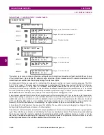
b) DIRECT INPUTS
PATH: SETTINGS
INPUTS/OUTPUTS
DIRECT
DIRECT INPUTS
REMOTE OUTPUTS
UserSt- 1 BIT PAIR
UserSt- 1 OPERAND:
Off
Range: FlexLogic operand
MESSAGE
UserSt- 1 EVENTS:
Disabled
Range: Disabled, Enabled
DEFAULT GSSE/GOOSE
UPDATE TIME: 60 s
Range: 1 to 60 s in steps of 1
DIRECT INPUTS
DIRECT INPUT 1-1
DEFAULT: Off
Range: Off, On
MESSAGE
DIRECT INPUT 1-2
DEFAULT: Off
Range: Off, On
MESSAGE
DIRECT INPUT 1-8
DEFAULT: Off
Range: Off, On
MESSAGE
DIRECT INPUT 2-1
DEFAULT: Off
Range: Off, On
MESSAGE
DIRECT INPUT 2-2
DEFAULT: Off
Range: Off, On
NOTE
NOTE
Summary of Contents for L30
Page 10: ...x L30 Line Current Differential System GE Multilin TABLE OF CONTENTS ...
Page 30: ...1 20 L30 Line Current Differential System GE Multilin 1 5 USING THE RELAY 1 GETTING STARTED 1 ...
Page 370: ...5 244 L30 Line Current Differential System GE Multilin 5 10 TESTING 5 SETTINGS 5 ...
Page 464: ...A 10 L30 Line Current Differential System GE Multilin A 1 PARAMETER LISTS APPENDIX A A ...
Page 600: ...C 30 L30 Line Current Differential System GE Multilin C 7 LOGICAL NODES APPENDIX C C ...
Page 610: ...D 10 L30 Line Current Differential System GE Multilin D 1 IEC 60870 5 104 APPENDIX D D ...
Page 622: ...E 12 L30 Line Current Differential System GE Multilin E 2 DNP POINT LISTS APPENDIX E E ...
Page 634: ...F 12 L30 Line Current Differential System GE Multilin F 3 WARRANTY APPENDIX F F ...
Page 644: ...x L30 Line Current Differential System GE Multilin INDEX ...

