6-18
L30 Line Current Differential System
GE Multilin
6.3 METERING
6 ACTUAL VALUES
6
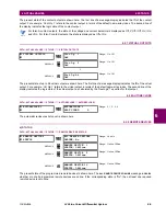
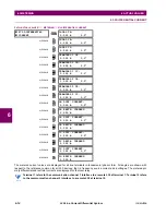
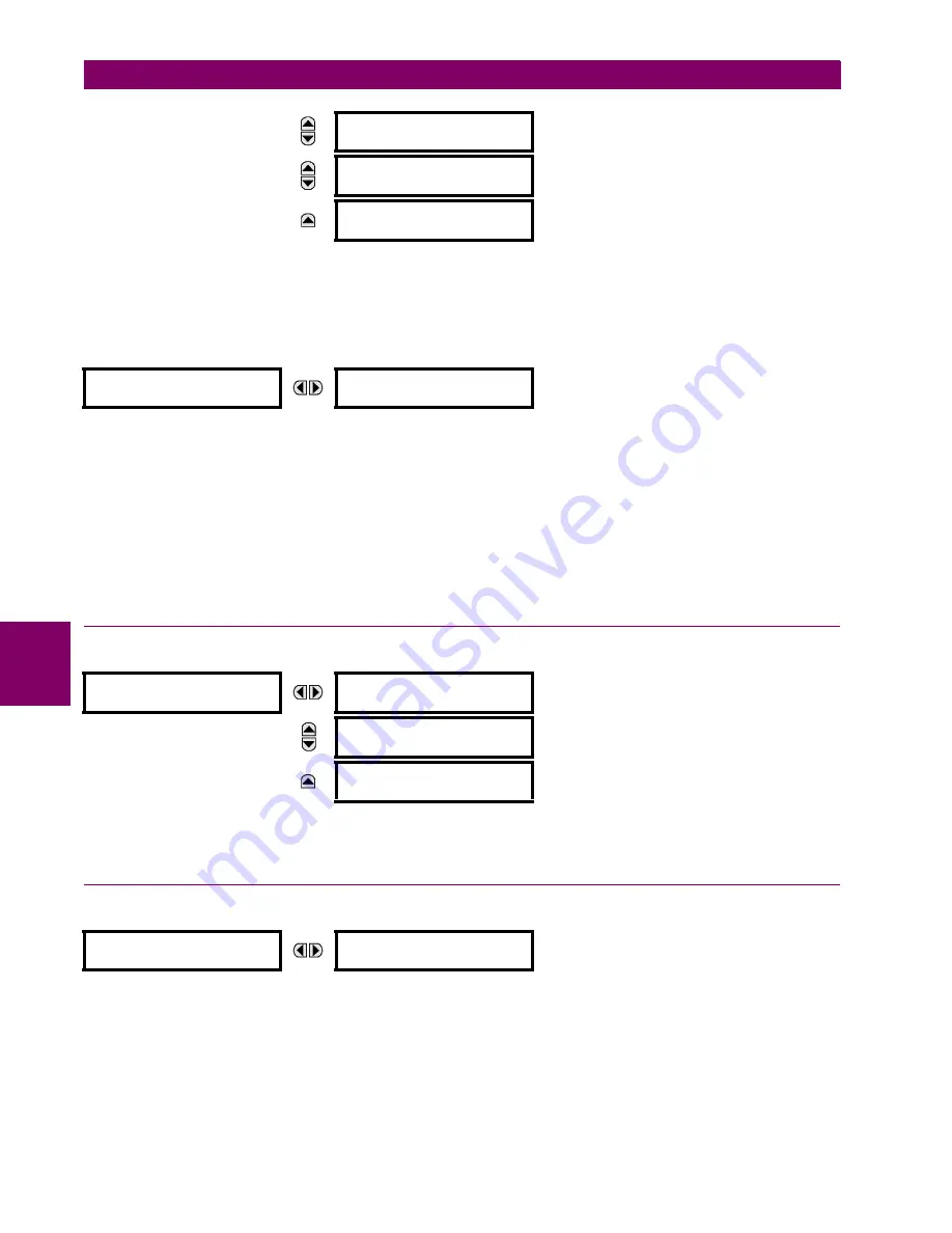
The metered values for real, reactive, and apparent power, as well as power factor, are displayed in this menu. The "SRC
1" text will be replaced by whatever name was programmed by the user for the associated source (see
SETTINGS
SYS-
TEM SETUP
SIGNAL SOURCES
).
g) FREQUENCY METERING
PATH: ACTUAL VALUES
METERING
SOURCE SRC 1
FREQUENCY
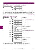
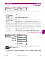
The metered frequency values are displayed in this menu. The "SRC 1" text will be replaced by whatever name was pro-
grammed by the user for the associated source (see
SETTINGS
SYSTEM SETUP
SIGNAL SOURCES
).
SOURCE FREQUENCY
is measured via software-implemented zero-crossing detection of an AC signal. The signal is either a
Clarke transformation of three-phase voltages or currents, auxiliary voltage, or ground current as per source configuration
(see the
SYSTEM SETUP
POWER SYSTEM
settings). The signal used for frequency estimation is low-pass filtered. The
final frequency measurement is passed through a validation filter that eliminates false readings due to signal distortions and
transients.
If the 87L function is enabled, then dedicated 87L frequency tracking is engaged. In this case, the relay uses the
METERING
TRACKING FREQUENCY
TRACKING FREQUENCY
value for all computations, overriding the
SOURCE FREQUENCY
value.
6.3.4 SYNCHROCHECK
PATH: ACTUAL VALUES
METERING
SYNCHROCHECK
SYNCHROCHECK 1(2)
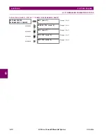
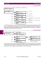
The actual values menu for synchrocheck 2 is identical to that of synchrocheck 1. If a synchrocheck function setting is "Dis-
abled", the corresponding actual values menu item will not be displayed.
6.3.5 TRACKING FREQUENCY
PATH: ACTUAL VALUES
METERING
TRACKING FREQUENCY
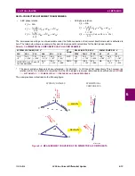
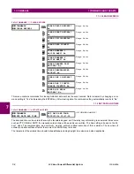
The tracking frequency is displayed here. The frequency is tracked based on configuration of the reference source. The
TRACKING FREQUENCY
is based upon positive sequence current phasors from all line terminals and is synchronously
adjusted at all terminals. If currents are below 0.125 pu, then the
NOMINAL FREQUENCY
is used.
MESSAGE
SRC 1 POWER FACTOR
a: 1.000
MESSAGE
SRC 1 POWER FACTOR
b: 1.000
MESSAGE
SRC 1 POWER FACTOR
c: 1.000
FREQUENCY
SRC 1
SRC 1 FREQUENCY:
0.00 Hz
SYNCHROCHECK 1
SYNCHROCHECK 1 DELTA
VOLT: 0.000
V
MESSAGE
SYNCHROCHECK 1 DELTA
PHASE: 0.0°
MESSAGE
SYNCHROCHECK 1 DELTA
FREQ: 0.00
Hz
TRACKING FREQUENCY
TRACKING FREQUENCY:
60.00 Hz
Summary of Contents for L30
Page 10: ...x L30 Line Current Differential System GE Multilin TABLE OF CONTENTS ...
Page 30: ...1 20 L30 Line Current Differential System GE Multilin 1 5 USING THE RELAY 1 GETTING STARTED 1 ...
Page 370: ...5 244 L30 Line Current Differential System GE Multilin 5 10 TESTING 5 SETTINGS 5 ...
Page 464: ...A 10 L30 Line Current Differential System GE Multilin A 1 PARAMETER LISTS APPENDIX A A ...
Page 600: ...C 30 L30 Line Current Differential System GE Multilin C 7 LOGICAL NODES APPENDIX C C ...
Page 610: ...D 10 L30 Line Current Differential System GE Multilin D 1 IEC 60870 5 104 APPENDIX D D ...
Page 622: ...E 12 L30 Line Current Differential System GE Multilin E 2 DNP POINT LISTS APPENDIX E E ...
Page 634: ...F 12 L30 Line Current Differential System GE Multilin F 3 WARRANTY APPENDIX F F ...
Page 644: ...x L30 Line Current Differential System GE Multilin INDEX ...


