GE Multilin
L30 Line Current Differential System
9-17
9 THEORY OF OPERATION
9.2 OPERATING CONDITION CHARACTERISTICS
9
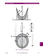
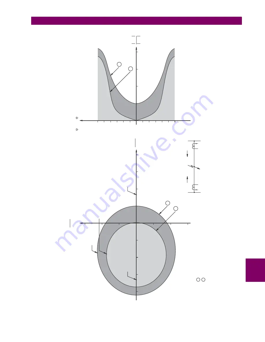
Figure 9–7: RESTRAINT CHARACTERISTICS
831726A1.CDR
(Angle
between
loc
and
re
m
is
ideally
0
for
inter
nal
fault)
II
o
1
-
For
re
m
=1.5
pu
and
angle
0-360
with
respect
to
loc
II
o
2
-
For
re
m
=
3
p
u
and
angle
0-360
with
respect
to
loc
II
o
OPERATE
I
loc
I
re
m
-3
II
loc
-
rem
180
150
120
90
60
30
-30
-60
-90
-120
-150
-180
1
2
3
4
0
I I
loc
re
m
RESTRAINT
RESTRAINT
1
2
Boundar
y
point
(angle
between
loc
and
re
m
about
130
)
II
o
T
rip
point
(angle
between
loc
and
re
m
0
)
II
o
Boundar
y
point
(angle
between
loc
and
re
m
about
140
)
II
o
OPERATE
1
2
I I
loc
re
m
Imaginary
-2
2
3
1
2
3
4
I I
loc
re
m
Real
-1
-2
Restraint
point
(angle
between
loc
and
re
m
180
)
II
o
-3
-4
1
-1
RESTRAINT
0
Summary of Contents for L30
Page 10: ...x L30 Line Current Differential System GE Multilin TABLE OF CONTENTS ...
Page 30: ...1 20 L30 Line Current Differential System GE Multilin 1 5 USING THE RELAY 1 GETTING STARTED 1 ...
Page 370: ...5 244 L30 Line Current Differential System GE Multilin 5 10 TESTING 5 SETTINGS 5 ...
Page 464: ...A 10 L30 Line Current Differential System GE Multilin A 1 PARAMETER LISTS APPENDIX A A ...
Page 600: ...C 30 L30 Line Current Differential System GE Multilin C 7 LOGICAL NODES APPENDIX C C ...
Page 610: ...D 10 L30 Line Current Differential System GE Multilin D 1 IEC 60870 5 104 APPENDIX D D ...
Page 622: ...E 12 L30 Line Current Differential System GE Multilin E 2 DNP POINT LISTS APPENDIX E E ...
Page 634: ...F 12 L30 Line Current Differential System GE Multilin F 3 WARRANTY APPENDIX F F ...
Page 644: ...x L30 Line Current Differential System GE Multilin INDEX ...

