3-12
L30 Line Current Differential System
GE Multilin
3.2 WIRING
3 HARDWARE
3
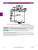
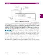
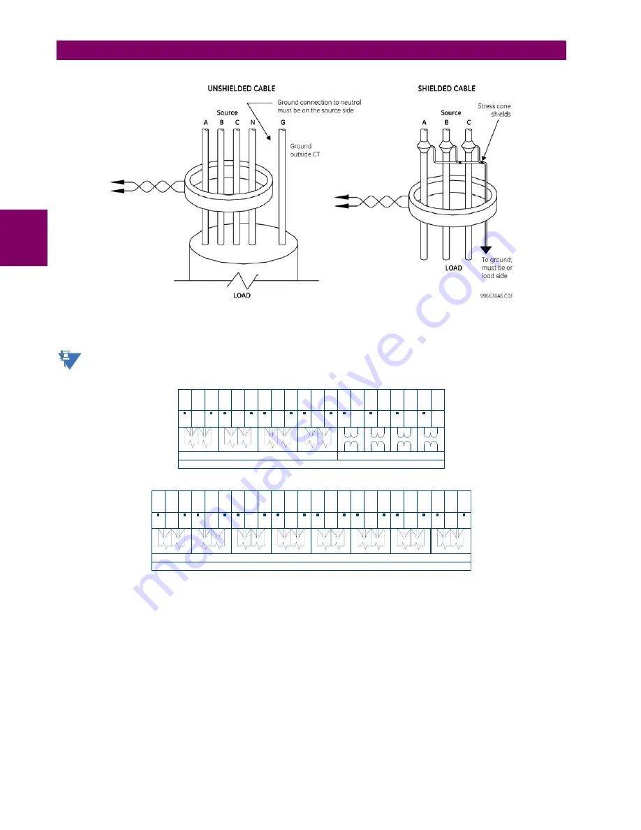
Figure 3–14: ZERO-SEQUENCE CORE BALANCE CT INSTALLATION
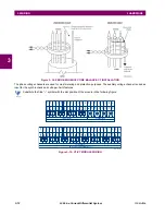
The phase voltage channels are used for most metering and protection purposes. The auxiliary voltage channel is used as
input for the synchrocheck and volts-per-hertz features.
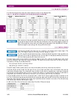
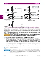
Substitute the tilde “~” symbol with the slot position of the module in the following figure.
Figure 3–15: CT/VT MODULE WIRING
NOTE
~
~
~
~
~
~
~
~
~
~
~
~
~
~
~
~
~
~
~
~
1a
1b
1c
2a
2b
2c
3a
4a
5a
6a
7a
8a
3b
4b
5c
6c
7c
8c
3c
4c
Current inputs
8F, 8G, 8L, and 8M modules (4 CTs and 4 VTs)
Voltage inputs
VA
VB
VC
VX
VA
VB
VC
VX
IA
IC
IB
IG
IA5
IC5
IB5
IG5
IA1
IC1
IB1
IG1
~
~
~
~
~
~
~
~
~
~
~
~
~
~
~
~
~
~
~
~
~
~
~
~
1a
5a
1b
5b
1c
5c
2a
6a
2b
6b
2c
6c
3a
7a
4a
8a
3b
7b
4b
8b
3c
7c
4c
8c
Current inputs
842766A3.CDR
IA
IA
IC
IC
IB
IB
IG
IG
IA5
IA5
IC5
IC5
IB5
IB5
IG5
IG5
IA1
IA1
IC1
IC1
IB1
IB1
IG1
IG1
8H, 8J, 8N, and 8R modules (8 CTs)
Summary of Contents for L30
Page 10: ...x L30 Line Current Differential System GE Multilin TABLE OF CONTENTS ...
Page 30: ...1 20 L30 Line Current Differential System GE Multilin 1 5 USING THE RELAY 1 GETTING STARTED 1 ...
Page 370: ...5 244 L30 Line Current Differential System GE Multilin 5 10 TESTING 5 SETTINGS 5 ...
Page 464: ...A 10 L30 Line Current Differential System GE Multilin A 1 PARAMETER LISTS APPENDIX A A ...
Page 600: ...C 30 L30 Line Current Differential System GE Multilin C 7 LOGICAL NODES APPENDIX C C ...
Page 610: ...D 10 L30 Line Current Differential System GE Multilin D 1 IEC 60870 5 104 APPENDIX D D ...
Page 622: ...E 12 L30 Line Current Differential System GE Multilin E 2 DNP POINT LISTS APPENDIX E E ...
Page 634: ...F 12 L30 Line Current Differential System GE Multilin F 3 WARRANTY APPENDIX F F ...
Page 644: ...x L30 Line Current Differential System GE Multilin INDEX ...


