GE Multilin
F60 Feeder Protection System
5-11
5 SETTINGS
5.2 PRODUCT SETUP
5
The
UNAUTHORIZED ACCESS
operand is reset with the
COMMANDS
CLEAR RECORDS
RESET UNAUTHORIZED
ALARMS
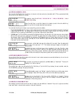
command. Therefore, to apply this feature with security, the command level should be password-protected. The
operand does not generate events or targets.
If events or targets are required, the
UNAUTHORIZED ACCESS
operand can be assigned to a digital element programmed
with event logs or targets enabled.
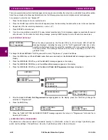
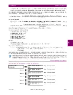
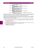
The access level timeout settings are shown below.
PATH: SETTINGS
PRODUCT SETUP
SECURITY
ACCESS SUPERVISION
ACCESS LEVEL TIMEOUTS
These settings allow the user to specify the length of inactivity required before returning to the restricted access level. Note
that the access level will set as restricted if control power is cycled.
•
COMMAND LEVEL ACCESS TIMEOUT
: This setting specifies the length of inactivity (no local or remote access)
required to return to restricted access from the command password level.
•
SETTING LEVEL ACCESS TIMEOUT
: This setting specifies the length of inactivity (no local or remote access)
required to return to restricted access from the command password level.
DUAL PERMISSION SECURITY ACCESS
PATH: SETTINGS
PRODUCT SETUP
SECURITY
DUAL PERMISSION SECURITY ACCESS
The dual permission security access feature provides a mechanism for customers to prevent unauthorized or unintended
upload of settings to a relay through the local or remote interfaces interface.
The following settings are available through the local (front panel) interface only.
•
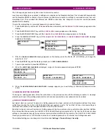
LOCAL SETTING AUTH
: This setting is used for local (front panel or RS232 interface) setting access supervision.
Valid values for the FlexLogic operands are either “On” (default) or any physical “Contact Input ~~ On” value.
If this setting is “On“, then local setting access functions as normal; that is, a local setting password is required. If this
setting is any contact input on FlexLogic operand, then the operand must be asserted (set as on) prior to providing the
local setting password to gain setting access.
If setting access is
not
authorized for local operation (front panel or RS232 interface) and the user attempts to obtain
setting access, then the
UNAUTHORIZED ACCESS
message is displayed on the front panel.
If this setting is "Off," firmware upgrades are blocked. If this setting is "On," firmware upgrades are allowed.
•
REMOTE SETTING AUTH
: This setting is used for remote (Ethernet or RS485 interfaces) setting access supervision.
If this setting is “On” (the default setting), then remote setting access functions as normal; that is, a remote password is
required). If this setting is “Off”, then remote setting access is blocked even if the correct remote setting password is
provided. If this setting is any other FlexLogic operand, then the operand must be asserted (set as on) prior to provid-
ing the remote setting password to gain setting access.
If this setting is "Off," firmware upgrades are blocked. If this setting is "On," firmware upgrades are allowed.
•
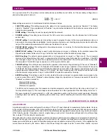
ACCESS AUTH TIMEOUT
: This setting represents the timeout delay for local setting access. This setting is applicable
when the
LOCAL SETTING AUTH
setting is programmed to any operand except “On”. The state of the FlexLogic operand
is continuously monitored for an off-to-on transition. When this occurs, local access is permitted and the timer pro-
grammed with the
ACCESS AUTH TIMEOUT
setting value is started. When this timer expires, local setting access is
ACCESS LEVEL
TIMEOUTS
COMMAND LEVEL ACCESS
TIMEOUT: 5 min
Range: 5 to 480 minutes in steps of 1
MESSAGE
SETTING LEVEL ACCESS
TIMEOUT: 30 min
Range: 5 to 480 minutes in steps of 1
DUAL PERMISSION
SECURITY ACCESS
LOCAL SETTING AUTH:
On
Range: selected FlexLogic operands (see below)
MESSAGE
REMOTE SETTING AUTH:
On
Range: FlexLogic operand
MESSAGE
ACCESS AUTH
TIMEOUT: 30 min.
Range: 5 to 480 minutes in steps of 1
Summary of Contents for F60
Page 10: ...x F60 Feeder Protection System GE Multilin TABLE OF CONTENTS ...
Page 30: ...1 20 F60 Feeder Protection System GE Multilin 1 5 USING THE RELAY 1 GETTING STARTED 1 ...
Page 138: ...4 28 F60 Feeder Protection System GE Multilin 4 2 FACEPLATE INTERFACE 4 HUMAN INTERFACES 4 ...
Page 454: ...5 316 F60 Feeder Protection System GE Multilin 5 10 TESTING 5 SETTINGS 5 ...
Page 500: ...7 14 F60 Feeder Protection System GE Multilin 7 1 COMMANDS 7 COMMANDS AND TARGETS 7 ...
Page 508: ...8 8 F60 Feeder Protection System GE Multilin 8 2 FAULT LOCATOR 8 THEORY OF OPERATION 8 ...
Page 522: ...10 12 F60 Feeder Protection System GE Multilin 10 6 DISPOSAL 10 MAINTENANCE 10 ...
Page 660: ...B 116 F60 Feeder Protection System GE Multilin B 4 MEMORY MAPPING APPENDIX B B ...
Page 706: ...E 10 F60 Feeder Protection System GE Multilin E 1 IEC 60870 5 104 APPENDIX E E ...
Page 718: ...F 12 F60 Feeder Protection System GE Multilin F 2 DNP POINT LISTS APPENDIX F F ...
Page 728: ...H 8 F60 Feeder Protection System GE Multilin H 2 ABBREVIATIONS APPENDIX H H Z Impedance Zone ...
Page 730: ...H 10 F60 Feeder Protection System GE Multilin H 3 WARRANTY APPENDIX H H ...

