5-260
F60 Feeder Protection System
GE Multilin
5.7 CONTROL ELEMENTS
5 SETTINGS
5
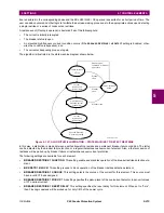
The algorithm is in “Normal” state when it detects no abnormal activity on the power system. While in the “Normal” state,
any one of several power system events (a high output of the Expert Arc Detector, a significant loss of load, or a Hi-Z over-
current) cause the algorithm to move to the “Coordination Timeout” state, where it remains for the time specified by the
OC
PROTECTION COORD TIMEOUT
setting. Following this interval, the algorithm moves into its “Armed” state. The criteria for
detecting arcing or a downed conductor are:
1.
the Expert Arc Detector Algorithm's output reaches a high level enough times, and
2.
its high level was last reached when the algorithm's state was “Armed”.
The “Arcing Sensitivity” setting determines what level constitutes a “high” output from the Expert Arc Detector Algorithm,
and the number that constitutes what “enough times” means. If these criteria are met, the algorithm temporarily moves to
either the “Arcing” state or the “Downed Conductor” state, the difference being determined by whether or not there was a
significant, precipitous loss of load (as determined by the
LOSS OF LOAD THRESHOLD
user setting) or a Hi-Z overcurrent (as
determined by the
PHASE OC MIN PICKUP
and
NEUTRAL OC MIN PICKUP
user settings). If either of these caused the algorithm
to move from its “Normal” state to its “Coordination Timeout” state, then the algorithm moves to the “Downed Conductor”
state temporarily. Otherwise, it temporarily moves to the “Arcing” state. After pulsing either of these outputs, the algorithm's
state returns to “Normal”. Also, if two minutes pass without high levels from the Expert Arc Detector Algorithm while the
algorithm is in its Armed state, then it moves from the “Armed” state directly back to the “Normal” state.
Two FlexLogic operands,
HI-Z ARMED
and
HI-Z DISARMED
, are created to represent the armed state of the Hi-Z element.
The
HI-Z ARMED
operand is on when the algorithm is in the armed state, whereas the
HI-Z DISARMED
operand is on when
the algorithm is not in the armed state. When the algorithm is armed, this also includes the arcing and downed conductor
states. When the algorithm is disarmed, this also includes the normal and coordination timeout states (as defined by Mod-
bus format F187 as described in
Appendix B
).
The Hi-Z settings are described below:
•
HI-Z SOURCE
: Selects the source for the RMS currents and voltages used in Hi-Z algorithms. The source should
include currents from the 8F/8G CT module and appropriate voltages. If the source does not include voltages, Voltage
Supervision is disabled.
•
HI-Z ARCING SENSITIVITY
: This setting establishes the belief-in-arcing confidence level at which the Hi-Z element
will recognize arcing and the number of times the algorithm must conform its belief in arcing before it produces an out-
put. The range is 1 to 10, where 10 is the most sensitive and 1 is the least sensitive setting.
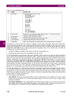
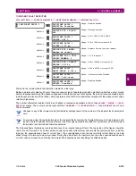
Table 5–36: HI-Z CAPTURE DATA
#
NAME
DESCRIPTION
1
StatusMask
Bit-mask of the algorithm state (16 bits)
BIT_ARCING
BIT_DOWNED_COND
BIT_ARC_TREND
BIT_PHASE_A
BIT_PHASE_B
BIT_PHASE_C
BIT_PHASE_N
BIT_IOC_A
BIT_IOC_B
BIT_IOC_C
BIT_IOC_N
BIT_LOL_A
BIT_LOL_B
BIT_LOL_C
BIT_I_DISTURBANCE
BIT_V_DISTURBANCE
2
AlgorithmState
Present value of the High-Z output state machine: Normal = 0, Coordination Timeout = 1,
Armed = 2, Arcing = 5, Downed Conductor = 9
3
EadZeroedFlag
Flag indicating the EAD table was cleared
4
SpectralFlag
Flag indicating the Spectral algorithm has found a match
5
ThreePhaseFlag
Flag indicating a three phase event was detected
6
PhaseInfo[4]
Phase specific information for the three phase currents and the neutral (see table below)
Summary of Contents for F60
Page 10: ...x F60 Feeder Protection System GE Multilin TABLE OF CONTENTS ...
Page 30: ...1 20 F60 Feeder Protection System GE Multilin 1 5 USING THE RELAY 1 GETTING STARTED 1 ...
Page 138: ...4 28 F60 Feeder Protection System GE Multilin 4 2 FACEPLATE INTERFACE 4 HUMAN INTERFACES 4 ...
Page 454: ...5 316 F60 Feeder Protection System GE Multilin 5 10 TESTING 5 SETTINGS 5 ...
Page 500: ...7 14 F60 Feeder Protection System GE Multilin 7 1 COMMANDS 7 COMMANDS AND TARGETS 7 ...
Page 508: ...8 8 F60 Feeder Protection System GE Multilin 8 2 FAULT LOCATOR 8 THEORY OF OPERATION 8 ...
Page 522: ...10 12 F60 Feeder Protection System GE Multilin 10 6 DISPOSAL 10 MAINTENANCE 10 ...
Page 660: ...B 116 F60 Feeder Protection System GE Multilin B 4 MEMORY MAPPING APPENDIX B B ...
Page 706: ...E 10 F60 Feeder Protection System GE Multilin E 1 IEC 60870 5 104 APPENDIX E E ...
Page 718: ...F 12 F60 Feeder Protection System GE Multilin F 2 DNP POINT LISTS APPENDIX F F ...
Page 728: ...H 8 F60 Feeder Protection System GE Multilin H 2 ABBREVIATIONS APPENDIX H H Z Impedance Zone ...
Page 730: ...H 10 F60 Feeder Protection System GE Multilin H 3 WARRANTY APPENDIX H H ...


