6-4
F60 Feeder Protection System
GE Multilin
6.2 STATUS
6 ACTUAL VALUES
6
6.2STATUS
For status reporting, ‘On’ represents Logic 1 and ‘Off’ represents Logic 0.
6.2.1 CONTACT INPUTS
PATH: ACTUAL VALUES
STATUS
CONTACT INPUTS
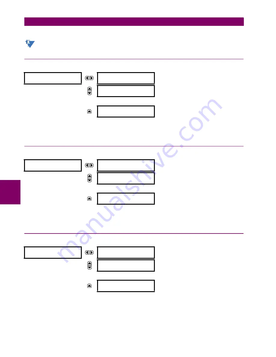
The present status of the contact inputs is shown here. The first line of a message display indicates the ID of the contact
input. For example, ‘Cont Ip 1’ refers to the contact input in terms of the default name-array index. The second line of the
display indicates the logic state of the contact input.
6.2.2 VIRTUAL INPUTS
PATH: ACTUAL VALUES
STATUS
VIRTUAL INPUTS
The present status of the 64 virtual inputs is shown here. The first line of a message display indicates the ID of the virtual
input. For example, ‘Virt Ip 1’ refers to the virtual input in terms of the default name. The second line of the display indicates
the logic state of the virtual input.
6.2.3 REMOTE INPUTS
PATH: ACTUAL VALUES
STATUS
REMOTE INPUTS
The present state of the 32 remote inputs is shown here.
The state displayed will be that of the remote point unless the remote device has been established to be “Offline” in which
case the value shown is the programmed default state for the remote input.
CONTACT INPUTS
Cont Ip 1
Off
Range: On, Off
MESSAGE
Cont Ip 2
Off
Range: On, Off
↓
MESSAGE
Cont Ip xx
Off
Range: On, Off
VIRTUAL INPUTS
Virt Ip 1
Off
Range: On, Off
MESSAGE
Virt Ip 2
Off
Range: On, Off
↓
MESSAGE
Virt Ip 64
Off
Range: On, Off
REMOTE INPUTS
REMOTE INPUT 1
STATUS: Off
Range: On, Off
MESSAGE
REMOTE INPUT 2
STATUS: Off
Range: On, Off
↓
MESSAGE
REMOTE INPUT 32
STATUS: Off
Range: On, Off
NOTE
Summary of Contents for F60
Page 10: ...x F60 Feeder Protection System GE Multilin TABLE OF CONTENTS ...
Page 30: ...1 20 F60 Feeder Protection System GE Multilin 1 5 USING THE RELAY 1 GETTING STARTED 1 ...
Page 138: ...4 28 F60 Feeder Protection System GE Multilin 4 2 FACEPLATE INTERFACE 4 HUMAN INTERFACES 4 ...
Page 454: ...5 316 F60 Feeder Protection System GE Multilin 5 10 TESTING 5 SETTINGS 5 ...
Page 500: ...7 14 F60 Feeder Protection System GE Multilin 7 1 COMMANDS 7 COMMANDS AND TARGETS 7 ...
Page 508: ...8 8 F60 Feeder Protection System GE Multilin 8 2 FAULT LOCATOR 8 THEORY OF OPERATION 8 ...
Page 522: ...10 12 F60 Feeder Protection System GE Multilin 10 6 DISPOSAL 10 MAINTENANCE 10 ...
Page 660: ...B 116 F60 Feeder Protection System GE Multilin B 4 MEMORY MAPPING APPENDIX B B ...
Page 706: ...E 10 F60 Feeder Protection System GE Multilin E 1 IEC 60870 5 104 APPENDIX E E ...
Page 718: ...F 12 F60 Feeder Protection System GE Multilin F 2 DNP POINT LISTS APPENDIX F F ...
Page 728: ...H 8 F60 Feeder Protection System GE Multilin H 2 ABBREVIATIONS APPENDIX H H Z Impedance Zone ...
Page 730: ...H 10 F60 Feeder Protection System GE Multilin H 3 WARRANTY APPENDIX H H ...


