GE Multilin
F60 Feeder Protection System
6-5
6 ACTUAL VALUES
6.2 STATUS
6
6.2.4 REMOTE DOUBLE-POINT STATUS INPUTS
PATH: ACTUAL VALUES
STATUS
REMOTE DPS INPUTS
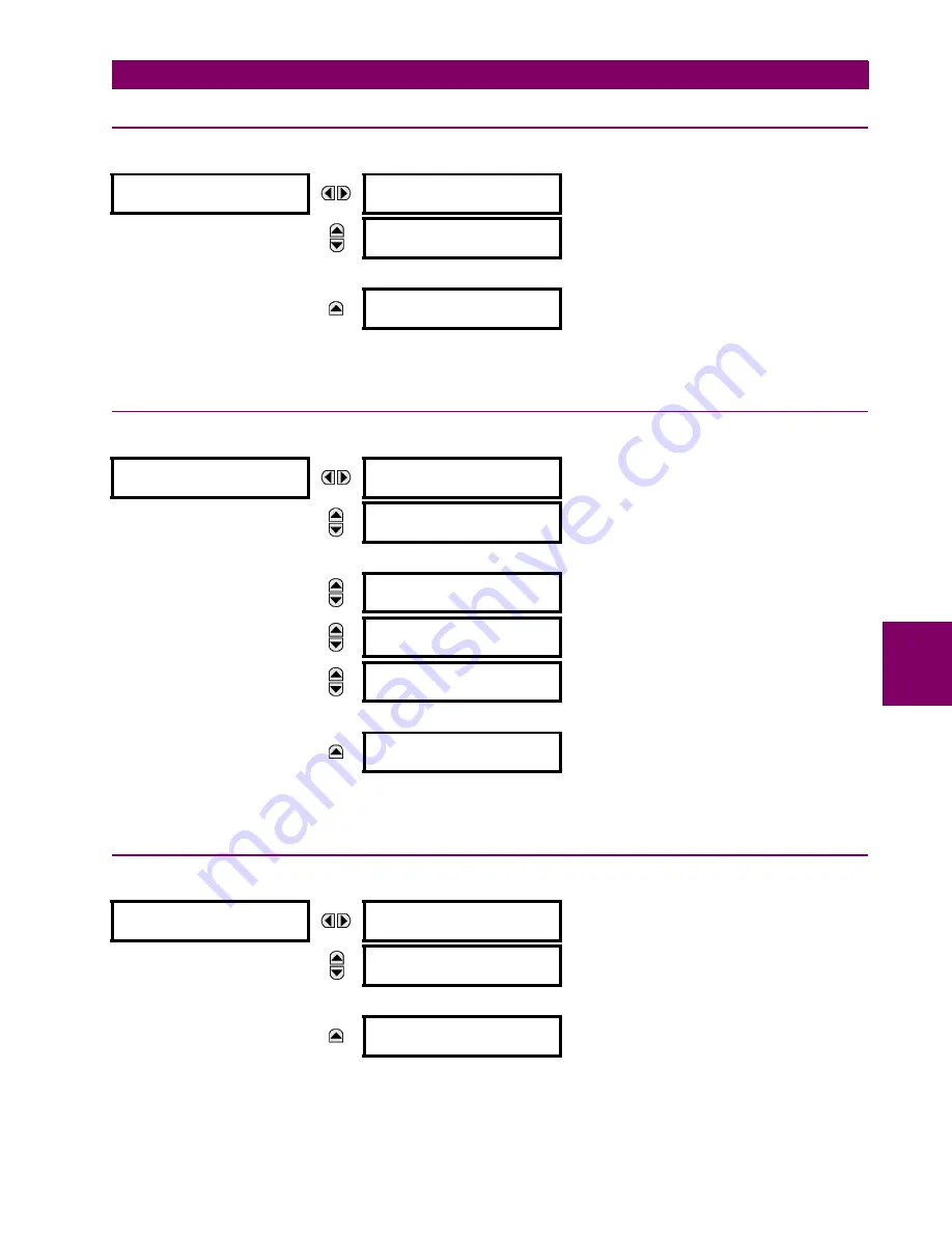
The present state of the remote double-point status inputs is shown here. The actual values indicate if the remote double-
point status inputs are in the on (close), off (open), intermediate, or bad state.
6.2.5 TELEPROTECTION INPUTS
PATH: ACTUAL VALUES
STATUS
TELEPROTECTION INPUTS
The present state of teleprotection inputs from communication channels 1 and 2 are shown here. The state displayed will
be that of corresponding remote output unless the channel is declared failed.
6.2.6 CONTACT OUTPUTS
PATH: ACTUAL VALUES
STATUS
CONTACT OUTPUTS
The present state of the contact outputs is shown here. The first line of a message display indicates the ID of the contact
output. For example, ‘Cont Op 1’ refers to the contact output in terms of the default name-array index. The second line of
the display indicates the logic state of the contact output.
REMOTE DPS INPUTS
REMOTE DPS INPUT 1
STATUS: Bad
Range: On, Off, Intermediate, Bad
MESSAGE
REMOTE DPS INPUT 2
STATUS: Bad
Range: On, Off, Intermediate, Bad
↓
MESSAGE
REMOTE DPS INPUT 5
STATUS: Bad
Range: On, Off, Intermediate, Bad
TELEPROTECTION
INPUTS
TELEPROTECTION
INPUT 1-1: Off
Range: Off, On
MESSAGE
TELEPROTECTION
INPUT 1-2: Off
Range: Off, On
↓
MESSAGE
TELEPROTECTION
INPUT 1-16: Off
Range: Off, On
MESSAGE
TELEPROTECTION
INPUT 2-1: Off
Range: Off, On
MESSAGE
TELEPROTECTION
INPUT 2-2: Off
Range: Off, On
↓
MESSAGE
TELEPROTECTION
INPUT 2-16: Off
Range: Off, On
CONTACT OUTPUTS
Cont Op 1
Off
Range: On, Off, VOff, VOn, IOn, IOff
MESSAGE
Cont Op 2
Off
Range: On, Off, VOff, VOn, IOn, IOff
↓
MESSAGE
Cont Op xx
Off
Range: On, Off, VOff, VOn, IOn, IOff
Summary of Contents for F60
Page 10: ...x F60 Feeder Protection System GE Multilin TABLE OF CONTENTS ...
Page 30: ...1 20 F60 Feeder Protection System GE Multilin 1 5 USING THE RELAY 1 GETTING STARTED 1 ...
Page 138: ...4 28 F60 Feeder Protection System GE Multilin 4 2 FACEPLATE INTERFACE 4 HUMAN INTERFACES 4 ...
Page 454: ...5 316 F60 Feeder Protection System GE Multilin 5 10 TESTING 5 SETTINGS 5 ...
Page 500: ...7 14 F60 Feeder Protection System GE Multilin 7 1 COMMANDS 7 COMMANDS AND TARGETS 7 ...
Page 508: ...8 8 F60 Feeder Protection System GE Multilin 8 2 FAULT LOCATOR 8 THEORY OF OPERATION 8 ...
Page 522: ...10 12 F60 Feeder Protection System GE Multilin 10 6 DISPOSAL 10 MAINTENANCE 10 ...
Page 660: ...B 116 F60 Feeder Protection System GE Multilin B 4 MEMORY MAPPING APPENDIX B B ...
Page 706: ...E 10 F60 Feeder Protection System GE Multilin E 1 IEC 60870 5 104 APPENDIX E E ...
Page 718: ...F 12 F60 Feeder Protection System GE Multilin F 2 DNP POINT LISTS APPENDIX F F ...
Page 728: ...H 8 F60 Feeder Protection System GE Multilin H 2 ABBREVIATIONS APPENDIX H H Z Impedance Zone ...
Page 730: ...H 10 F60 Feeder Protection System GE Multilin H 3 WARRANTY APPENDIX H H ...


