Kalatel CBR-PB3-WD 6 0150-0261A
2 Before You Begin
2.1 Installation Summary
The basic steps to install the CBR-PB3-WD unit are:
1. Connect the PB3 to the Receipt Printer using the supplied cable. (If
more than two PB3 units are used, verify that proper termination is set
on each individual PB3 unit.
2. Connect the PB3 to the DVMRe-CT/eZT/StoreSafe unit using the
supplied cable (RJ45-to-RJ45). (If your unit is a DVMRe-CD/CS, the
required interconnect cable is also provided (RJ45-to-DB9 - see Section
11 for the specific requirements for the DVMRe-CD/CS).
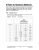
3. On each PB3, set the Camera ID switches for each PB3 that is to be
associated with a specific camera.
4. Program the DVMRe unit to record in the way desired to meet your
specific sites.
2.2 How to Use this Manual
We recommend that at least the following pages be reviewed before attempting
an installation.
q
ProBridge 3 Diagram on
page 9.
q
Connection Diagram on
page 11.
q
Installation & Configuration on
pages 13-15.
2.3 Kalatel Components:
(1) CBR-PB3-WD ProBridge includes:
•
(1) CBR-PB3-WD ProBridge unit.
•
(1) P/N 4310-0034B: RJ45 to RJ45 cable. Connects the ProBridge to
RS-485 Network. This cable is 6’ in length.
•
(1) P/N 4310-0047B: RJ45 to DB9F cable. Connects the ProBridge to
the DVMRe. This cable is 6’ in length.
•
(1) P/N 4310-0078A: DB9F to DB9M to DB9F ‘Y’ cable. Connects the
ProBridge to the Electronic Cash Register (ECR) and the Receipt
Printer This cable is 6’ in length.
•
(1) P/N 4010-0007: 12VDC 120VAC Power Supply or
(1) P/N 4010-0008: 12VDC 220VAC Power Supply.
•
(1) P/N 0150-0261A: Product Overview and Installation Manual.


