background image

Instruction Manual

S734DV & S7734DV

FIBER-OPTIC SYSTEM

FOUR-CHANNEL VIDEO AND 

MULTI-PROTOCOL  DATA

GE Interlogix

Fiber Options

g

x

Summary of Contents for S734DV

Page 1: ...Instruction Manual S734DV S7734DV FIBER OPTIC SYSTEM FOUR CHANNEL VIDEO AND MULTI PROTOCOL DATA GE Interlogix Fiber Options g ...

Page 2: ...tion of this equipment in a residential area is likely to cause interference in which case the user will be required to take whatev er means may be necessary to correct the interference at his own expense Changes or modifications not expressly approved by the party responsible for compliance could void the user s authority to operate the equipment This apparatus does not exceed the Class A limits ...

Page 3: ...rials in case it becomes neces sary to return the unit INSTALLATION Installation Considerations This fiber optic link is supplied as a standalone module or as a rack card Units should be installed in dry locations protected from extremes of temperature and humidity Standalone Modules 1 Determine where the module will be installed and ensure that there is adequate space at both ends for making the ...

Page 4: ...nnector Orient the card so that it will seat in the socket and slide it into the enclosure until the edge con nector at the back of the card seats in the socket Seating may require thumb pressure on the top and bottom of the card s front panel CAUTION Take care not to press on any of the LEDs 2 Tighten the two thumb screws on the card until the front panel of the card is seated against the front o...

Page 5: ...V 9 RS 485 4 wire standard A RS 485 4 wire 1V B RS 485 4 wire 2V C Reserved D Reserved E Reserved F Test Mode Tx F 1 0 E D 2 3 5 6 7 8 C B A 9 4 FIGURE 3 DATA SELECT SWITCH SETTINGS FIGURE 4 RACK MOUNT RECEIVER SWITCH AND JUMPER LOCATION VIDEO CARD ALARM 1 ON 2 OFF TEST 1 NTSC 2 PAL 3 OFF 1 2 1 2 3 JP1 DATA CARD DATA SELECT SWITCH SW1 8 1 DATA CONNECTOR RELAY CONTACT 1 2 CONNECTOR RELAY CONTACT 3 ...

Page 6: ...jumper JP1 on the receiver or JP4 on the transmitter to the OFF position Refer to Figures 4 and 5 NOTE Setting alarm to OFF inactive does not affect the operation of the LEVEL LOSSTM LED Loss of optical signal will always be indicated by a red LEVEL LOSSTM LED www fiberoptions com fiber ge interlogix com free phone 800 342 3748 free fax 877 342 3732 4 FIGURE 5 RACK MOUNT TRANSMITTER SWITCH AND JUM...

Page 7: ...e failure conditions or when using the Test Mode described on page 9 Data Translation The data translation capability of the S734DV series is unique in the industry It allows translation from one format to anoth er thus eliminating the need for external translation devices Data translation examples are shown in Table 1 The translation is in the physical layer only it cannot interpret specific prot...

Page 8: ...22 1 4 Single Ended to Differential Conversion RS 422 Æ RS 232 3 wire 4 1 Differential to Single Ended Conversion RS 232 5 wire Æ RS 485 2 7 A RS 232 Handshaking bit is used to indicate tri state RS 485 Æ RS 232 5 wire 7 A 2 Tri State detection circuitry activates handshaking bit DATA EQUIPMENT DATA OUT DATA IN FIBER LINK DATA OUT DATA IN CONTACT OUT CONTACT IN CONTACT OUT CONTACT IN C2 C1 C1 C2 C...

Page 9: ...fset Mode Switch SW1 RS 485 2 Wire Interface Position 7 1V offset Position 6 standard offset Pin No Function 8 Ground 7 RS 485 termination tie to pin 5 6 RS 485 in 5 RS 485 in 4 5 VDC BIAS OUT 3 RS 485 out 2 RS 485 out 1 Ground Shield Position B 2V offset Mode Switch SW1 RS 485 4 Wire Interface Position A 1V offset Position 9 standard offset Pin No Function 8 Ground 7 nc 6 Manchester Biphase in 3 ...

Page 10: ...is the same one that is connected to the far end The proper optical connection will link the transmitter s TRANSMIT OUT port to the receiver s RECEIVE IN port See Figures 6 and 8 1 Wipe the inside of the port s sleeve with a lint free pipe cleaner moistened with reagent grade isopropyl alcohol Blow dry with dry air 2 Clean the connector using a lint free cloth dampened with alcohol to thoroughly w...

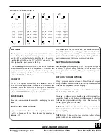
Page 11: ... indicating that a valid data for mat has not been selected b The DATA OUT LED is slowly flashing between amber green and off This indicates that the fiber path from the trans mitting unit is set for TEST MODE is reliable c The DATA IN LED should be off since there is no input copper connection made d The LEVEL LOSSTM LED is green indicating that suffi cient optical power is being received When th...

Page 12: ... mode has been selected or flashing red green indicates that NO mode has been selected RS 485 APPLICATION NOTES The S734DV is configurable for both full duplex 4 wire and half duplex 2 wire operation It can be used for interfacing to systems adhering strictly to the RS 485 specification and for use with systems that use a modified fail safe biased RS 485 bus Connection Use high quality twisted pai...

Page 13: ...fer to LED OPERATION on page 9 and Table 12 MAINTENANCE There is no operator maintenance other than keeping the units clean CONTACTING FIBER OPTIONS If you cannot determine the cause of your problem and are in the U S or Canada call the Fiber Options Headquarters in Bohemia NY If you are outside the U S or Canada call the closest interna tional office listed on the back page of this manual Have th...

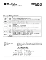
Page 14: ...fficient optical power received No action required LEVEL LOSS Red Insufficient optical power received Verify fiber connected within optical budget receiver power on Green Laser is operating normally No action required LASER Red Laser is malfunctioning Contact Fiber Options Green Valid video signal at unit No action required VIDEO IN OUT Red No video signal at unit Verify video connected video sour...

Reviews: