www.fiberoptions.com
fiber@ge-interlogix.com
free phone: 800.342.3748
free fax: 877.342.3732
9
Also, a special “ramp” test pattern can be generated when the
S734DVT is placed in test mode.
This will verify proper functionality of the digital decoding
process as well as troubleshooting fiber optic interconnections.
To enable the test pattern generator, refer to Video Format/Test
Pattern Generator on page 5:
Test Mode
Test mode allows the user to verify the operation of the copper
receiver/driver circuit in an S734DV, as well as the fiber con-
nection from one S734DV to another. This allows the fiber
optic video path to be tested without a video source. Using the
test mode is simple:
1. On one of the S734DV units, set the rotary DATA SELECT
switch to position F (TEST MODE). At this end only, wire the
data connector as shown in Table 10.
NOTE:
The unit set to position F (TEST MODE) is the trans-
mitter during testing.
2. At the opposite end, set the S734DV rotary DATA SELECT
switch to position 9.
3. In the test mode, the test transmitter unit should behave as
follows:
a. The ENABLED LED is red, indicating that a valid data for-
mat has not been selected.
b. The DATA OUT LED is slowly flashing between amber,
green, and off. This indicates that the test mode is generating
an output pattern and sending it out on copper.
c. The DATA IN LED should mimic the DATA OUT LED.
This indicates that the data transmit/receive circuitry is work-
ing properly.
d. The LEVEL/LOSS
TM
LED indicates received fiber signal
strength.
4. The test receiver (position 9) should behave as follows:
a. The ENABLED LED is red, indicating that a valid data for-
mat has not been selected.
b. The DATA OUT LED is slowly flashing between amber,
green, and off. This indicates that the fiber path from the trans-
mitting unit is set for TEST MODE is reliable.
c. The DATA IN LED should be off since there is no input
copper connection made.
d. The LEVEL/LOSS
TM
LED is green indicating that suffi-
cient optical power is being received.
When the test is completed, run the test again in the opposite
direction by changing DATA SELECT switch positions and
connectors. Successful completion of the test indicates both
units are operating correctly.
LED Operation
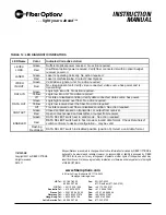
Refer to the Table 12 for an explanation of how to diagnose
system faults using the LEDs built into the Fiber Options units.
The S734DV has 7 LED indicators that are very useful in
describing the current state of operation, as well as the current
status of data flow and fiber optic signal strength. These indi-
cators are LASER, LEVEL /LOSS
TM
, VIDEO IN (or OUT),
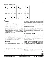
DATA IN (or OUT), CONTACT, and ENABLED. See Figure
9. They function as follows:
LASER Indicator
The LASER LED indicates the status of the laser. A green
LASER LED indicates the laser is operating normally. A red
LASER LED indicates the laser is malfunctioning.
LEVEL/LOSS
TM
Indicator
This LED is useful for indicating the relative optical signal
strength at the fiber optic receiver. When sufficient optical
power is being received, the LED is green. If no or insufficient
optical power is received, the LED will be red. All data will
default to it's failure state level to eliminate bus contention.
TABLE 11: ON SCREEN DIAGNOSTICS
Monitor Display
Meaning
Single white bar
No video input to transmitter
Double white bar
No optical input to receiver
Ramp test pattern
Testmode (Position E or F) selected at transmitter


