www.fiberoptions.com
fiber@ge-interlogix.com
free phone: 800.342.3748
free fax: 877.342.3732
5
Video Format/Test Pattern Generator
The S734DV links support both NTSC and PAL video stan-
dards without adjustment. The S734DVT transmitter and
S734DVR receiver have jumpers or a switch to select the video
format for the test pattern generator. To set the video format for
the test pattern generator:
NOTE:
In order for the test pattern generator to operate prop-
erly, both the transmitter and receiver must be set to the same
format.
1. Set jumper JP1 on the receiver board to position 1 for
NTSC, position 2 for PAL, or position 3 to disable the test pat-
tern generator. See Figure 4.
2. (Rack-mount transmitter only) Set jumper JP1 on the trans-
mitter to the NTSC, PAL, or disabled position as required. See
Figure 5.
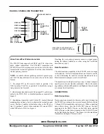
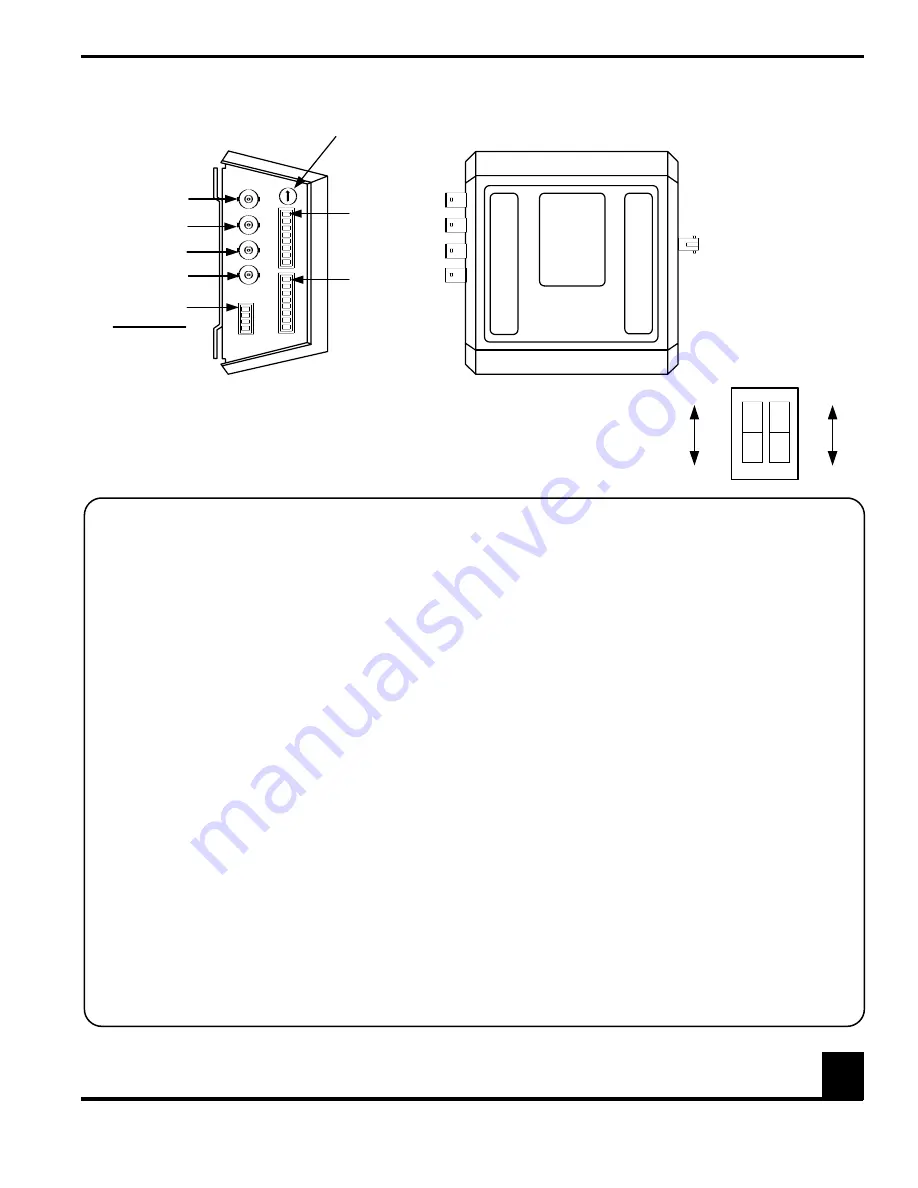
3. (Standalone transmitter only) Switch S1, located through
mounting hole on back of unit, configures the test pattern gen-
erator. Position 1 enables test patterns when in the ON posi-
tion. S1 position 2 selects video standard; ON selects NTSC,
while OFF selects PAL. See Figure 6.
Disabling the test pattern generator causes no signal output
during the failure conditions or when using the Test Mode
described on page 9.
Data Translation
The data translation capability of the S734DV series is unique
in the industry. It allows translation from one format to anoth-
er, thus eliminating the need for external translation devices.
Data translation examples are shown in Table 1.
The translation is in the physical layer only; it cannot interpret
specific protocols, nor translate commands. Due to the encod-
ing schemes utilized in Manchester and Biphase, these formats
are exempt from translation.
CONNECTIONS
Data Connections
Data connections are made to the removable screw terminal on
the S734DV according to the selected format. Refer to Tables
2 through 10 for transmitters and receivers. When connecting
data cables, always wire the DATA OUT pins on the data
equipment to the DATA IN pins on the fiber links, and the
DATA IN pins on the data equipment to the DATA OUT pins
on the fiber links. See Figure 7. See Figure 6 for the standalone
transmitter and Figure 8 for rack cards.
FIGURE 6: STANDALONE TRANSMITTER
DATA SELECT SWITCH
VIDEO IN 1
DATA
CONNECTOR
PIN 1
CONTACT
CLOSURE
CONNECTOR
VIDEO IN 2
VIDEO IN 3
VIDEO IN 4
POWER
CONNECTOR
PIN 1
12 - 16 VDC
PIN 2
24 VAC
PIN 3
24 VAC
PIN 4
DC GROUND
OPTICAL
(FIBER)
CONNECTOR
VIDEO TEST PATTERN SELECT
(LOCATED ON REAR OF MODULE)
ENABLE
DISABLE
1
2
ON
NTSC
PAL


