background image

05-4446A01, Rev. E

Mercury Reference Manual

95

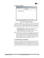
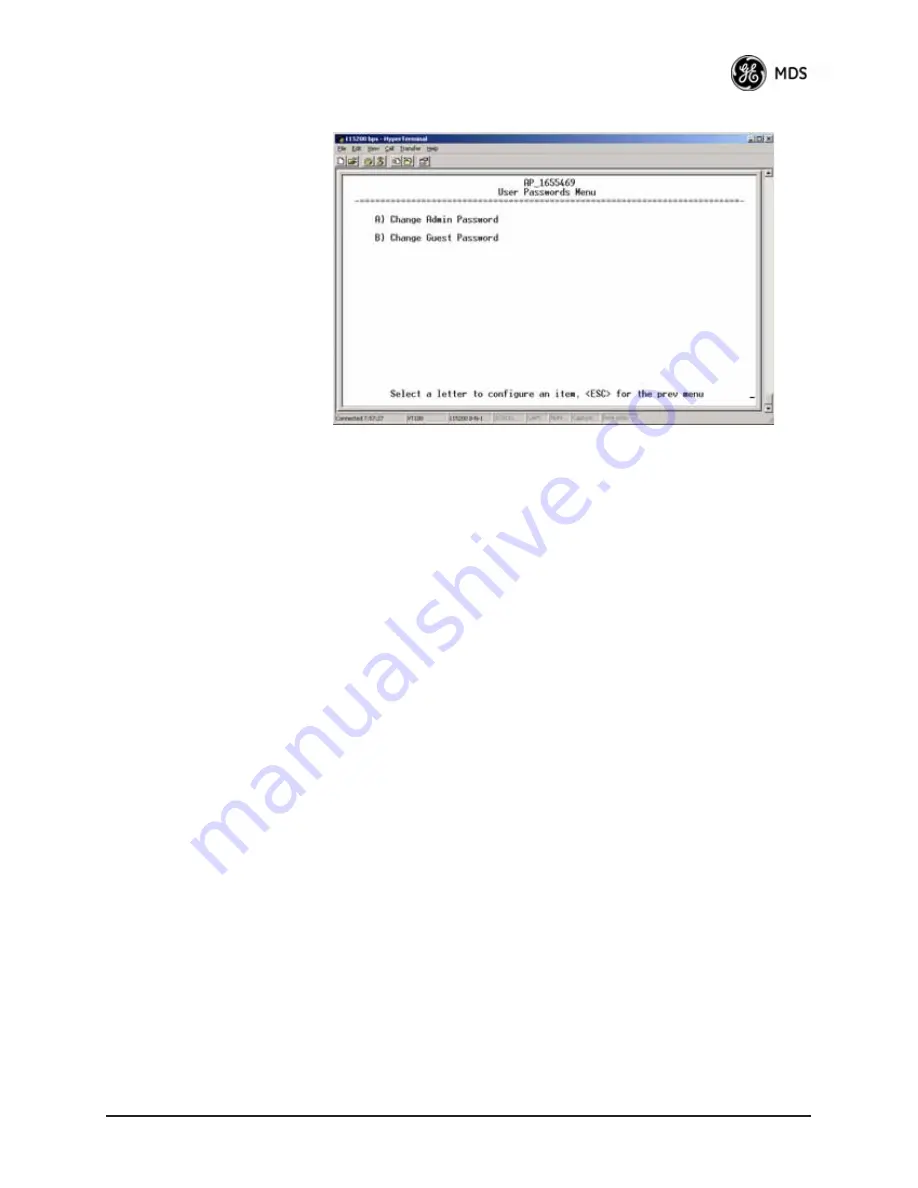
User Passwords Menu

Invisible place holder

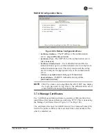
Figure 3-63. User Passwords Menu

To change the Administrator or Guest password, select the appropriate 
menu item (A or B). A flashing cursor appears to the right. From here, 
type the new password, which can be any alpha-numeric string up to 13 
characters long. The change is asserted when you press the Return key.

Change Admin Password

—Allows you to set a new password. 

[

any alpha-numeric string up to 13 characters; admin

]

Change Guest Password

—Allows you to set a new password. 

[

any alpha-numeric string up to 13 characters; guest

]

TIP:

For enhanced security, consider using misspelled words, a combi-

nation of letters and numbers, and a combination of upper and 
lower case letters. Also, the more characters used (up to 13), the 
more secure the password. These strategies help protect against 
sophisticated hackers who use a database of common words (for 
example, dictionary attacks) to determine a password.

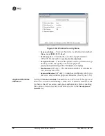
3.7.2 Wireless Security Menu

The features in the Wireless Security menu (

Figure 3-64 on Page 96

control the communication of data across the wireless link. You can 
authenticate the radios locally via a list of authorized radios, or remotely 
via a centralized IEEE 802.1x device authentication server. This server 
provides a centralized authentication mechanism based on standards.

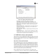
Summary of Contents for Mercury 3650

Page 1: ...Reference Manual 05 4446A01 Rev E MARCH 2009 Wireless IP Ethernet Transceiver Covering all AP and Remote Units including Mercury 900 3650 and Option Set 1 Remotes MDS MercuryTM Series ...

Page 2: ...ta System 9 1 3 2 Wireless LAN 10 1 3 3 Point to Point LAN Extension 11 1 3 4 Serial Radio Network Connectivity 11 1 3 5 Multiple Protocols and or Services 11 1 3 6 Wireless LAN with Mixed Services 12 1 3 7 Upgrading Older Wireless Network with Serial Interfaces 13 1 4 NETWORK DESIGN CONSIDERATIONS 14 1 4 1 Extending Network Coverage with Repeaters 14 1 4 2 Protected Network Operation using Multip...

Page 3: ... 2 PC Connection and Log In Procedures 36 3 2 3 Navigating the Menus 40 3 3 BASIC OVERVIEW OF OPERATION 42 3 3 1 Starting Information Screen 42 3 3 2 Main Menu 43 3 4 CONFIGURING NETWORK PARAMETERS 45 3 4 1 Network Configuration Menu 45 3 4 2 Ethernet Port Configuration Menu 56 3 4 3 Bridge Configuration 58 3 4 4 SNMP Agent Configuration 58 3 4 5 AP Location Push Config Menu 60 3 4 6 SNTP Server C...

Page 4: ...MEASUREMENTS 147 4 1 TROUBLESHOOTING 149 4 1 1 Interpreting the Front Panel LEDs 149 4 1 2 Troubleshooting With the Embedded Management System 150 4 1 3 Using Logged Operation Events 153 4 1 4 Alarm Conditions 154 4 1 5 Correcting Alarm Conditions 155 4 1 6 Logged Events 155 4 2 RADIO RF MEASUREMENTS 157 4 2 1 Antenna System SWR and Transmitter Power Output 157 4 2 2 Antenna Aiming For Directional...

Page 5: ...s that are cost effective innovative reliable and of the highest quality possible We promise to build a relationship that is forthright and ethical one that builds confidence and trust Related Materials on the Internet Data sheets frequently asked questions case studies applica tion notes firmware upgrades and other updated information is available on the GE MDS Web site at www GEmds com About GE ...

Page 6: ... power level is low the concentrated energy from a directional antenna may pose a health hazard Do not allow people to come closer than 23 cm 9 inches to the antenna when the transmitter is operating in indoor or outdoor environments More information on RF exposure is on the Internet at www fcc gov oet info documents bulletins To meet co location requirements the FCC requires a 20cm 7 87 inch sepa...

Page 7: ...ring or replacement with non factory components may adversely affect the safe use of the transceiver in hazardous locations and may void the approval A power connector with screw type retaining screws as supplied by GE MDS must be used Do not disconnect equipment unless power has been switched off or the area is known to be non hazardous Refer to Articles 500 through 502 of the National Electrical...

Page 8: ...are working with While every reasonable effort has been made to ensure the accuracy of this guide product improvements may also result in minor differences between the manual and the product shipped to you If you have additional questions or need an exact specification for a product please contact our Customer Service Team using the information at the back of this guide In addition manual updates ...

Page 9: ...viii Mercury Reference Manual 05 4446A01 Rev E ...

Page 10: ...g 8 1 2 4 External GPS PPS Option 9 1 3 APPLICATIONS 9 1 3 1 Mobile Fixed Data System 9 1 3 2 Wireless LAN 10 1 3 3 Point to Point LAN Extension 11 1 3 4 Serial Radio Network Connectivity 11 1 3 5 Multiple Protocols and or Services 11 1 3 6 Wireless LAN with Mixed Services 12 1 3 7 Upgrading Older Wireless Network with Serial Interfaces 13 1 4 NETWORK DESIGN CONSIDERATIONS 14 1 4 1 Extending Netwo...

Page 11: ...2 Mercury Reference Manual 05 4446A01 Rev E ...
Page 12: ...ls many users need access to documents electronically This is especially useful when you need to access docu mentation while traveling or want to share a document with another user in the field Electronic documents also allow searching for a spe cific term or subject especially in larger manuals Access manuals for our equipment anytime from our Web site at www GEmds com Simply click the Downloads ...

Page 13: ...ents where reliability and range are paramount The transceivers are commonly used to convey text documents graphics e mail video Voice over IP VoIP and a variety of other application data between mobile fixed point and WAN LAN based entities Based on multi carrier Orthogonal Frequency Division Multiplexing OFDM the transceiver features high speed low latency basic Quality of Service QoS for priori...

Page 14: ...me are inherent in the radio s operation such as the use of 900 MHz spread spectrum transmissions others include AES data encryption enabling disabling channels IEEE 802 1X port blocking approved device lists secure devices management protocols and password pro tection Security is not a one step process that can simply be turned on and for gotten It must be practiced and enforced at multiple level...

Page 15: ...istances in dense high interference environments Robust Network Security Prevents common attack schemes and hardware from gaining access or control of the network Common attack events are logged and reported by alarms Transmission Speed Operation at 1 5 Mbps is over 100 times faster than 9 6 kbps radios Plug and Play Connectivity AP or Remote configuration requires minimal setup Built in GPS Recei...

Page 16: ...requires GPS for TDD synchronization of the Access Points which may or may not be needed for an installation Access Point or Remote Identification Tip The outward appearance of AP and Remote radios is nearly identical however the hardware for each type is different and they are not inter changeable An quick way to identify them is to observe the color of the gasket seal in the center of the radio ...

Page 17: ...d Remote 802 11 WiFi Module Specifications The specifications listed below are unique to Remotes with Option Set 1 which contain a 2 4 GHz WiFi module SPECIFICATIONS on Page 178 contains a complete list of general Mercury Series specifica tions Protocol IEEE 802 11b g OFDM 6 to 54Mbps CCK 1 to 11Mbps Frequency Range 2400 to 2500MHz Maximum Transmit Power 15 dBm Permissible Antennas MDS 97 4278A36 ...

Page 18: ... electrical specifications in the External GPS PPS Option section on Page 180 This option is only available in hardware revision 1 0 2 or later 1 3 APPLICATIONS The following sections provide illustrations of typical transceiver instal lations This is an overview only A Network Administrator should be involved in all installation planning activities 1 3 1 Mobile Fixed Data System Mercury transceiv...

Page 19: ...s are exchanged at the Ethernet level This includes all types of IP traffic A Remote transceiver can only communicate over the air to an Access Point AP Peer to peer communications between Remotes can only take place indirectly via the AP In the same fashion an AP can only communicate over the air to associated Remote units Exception Two APs can communicate with each other off the air through thei...

Page 20: ...format A Remote transceiver with its serial port connected to a GE MDS serial based radio such as the MDS x790 x710 MDS TransNET and others provides a path for bringing the data from the older radio into the IP Ethernet environment of a Mercury based system Invisible place holder Figure 1 7 Backhaul Network 1 3 5 Multiple Protocols and or Services Prior to the introduction of Ethernet IP based rad...

Page 21: ...over Ethernet and IP such as video for remote surveillance 1 3 6 Wireless LAN with Mixed Services The transceiver is an excellent solution for a long range industrial wire less LAN It offers several advantages over commercial solutions pri marily improved performance over extended distances The rugged construction of the radio and its extended temperature range make it an ideal solution even in ha...

Page 22: ...for licensed and license free operation many of them manufac tured by GE MDS There are several ways that these systems can benefit from incorporating Mercury equipment The chief advantages are inter face flexibility serial and Ethernet in one unit and higher data throughput By taking advantage of its built in serial and Ethernet inter faces the transceiver is well suited to replace leased lines di...

Page 23: ...overcome with a repeater station Option A Using two transceivers to form a repeater station back to back repeater Although the range between fixed transceivers can be up to 40 km 25 miles over favorable terrain it is possible to extend the range consider ably by connecting two units together at one site in a back to back fashion creating repeater as shown in Figure 1 10 Use this arrangement whenev...

Page 24: ...This takes advan tage of the minimal radiation exhibited by most antennas directly above and below their driven elements Another interference reduction technique is to cross polarize the repeater antennas If one antenna is mounted for polarization in the ver tical plane and the other in the horizontal plane an additional 20 dB of attenuation is achieved The corresponding stations should use the sa...

Page 25: ...figu rations In a point to multipoint scenario the Access Point services multiple remotes A problem in the Access Point will have an effect on all remotes since none will have access to the network When operation of the network does not tolerate any down time it is possible to set up a protected configuration for the Access Point to greatly reduce the possi bility of this occurrence Two or more Ac...

Page 26: ... information see Frequency Control Menu on Page 67 NOTE Transceivers are shipped with the Network Name set to MDS Mercury as a factory default Can radio frequency interference RFI disrupt my wireless network When multiple radio networks operate in close physical proximity to other wireless networks individual units may not operate reliably under weak signal conditions and may be influenced by stro...

Page 27: ... Failed loginlockdown After five tries the transceiver ignores login requests for 5 minutes Critical event reports traps are generated as well Denial of service where Remote radios could be reconfigured with bad parameters bringing the network down Remote login with SSH or HTTPS Local console login Disabled HTTP and Telnet to allow only local management services Airsnort and other war driving hack...

Page 28: ...rge diameter coaxial cables 97 1677A159 3 ft 1m 97 1677A160 6 ft 1 8m Ethernet RJ 45 Crossover Cable CAT5 Cable assembly used to cross connect the Ethernet ports of two transceivers used in a repeater configuration Cable length 3 ft 1M 97 1870A21 2 Pin Power Plug Mates with power connector on transceiver Screw terminals provided for wires threaded locking screws to prevent accidental disconnect 73...

Page 29: ...ly 6 ft 1 8 m for connection of equipment or other EIA 232 serial devices previously connected to legacy units Consult factory for other lengths and variations 97 3035A06 Bandpass Filter Antenna system filter that helps eliminate interference from nearby paging transmitters 20 2822A02 Ethernet Surge Suppressor Surge suppressor for protection of Ethernet port against lightning 29 4018A01 Table 1 3 ...

Page 30: ...T THE ANTENNA PORTS 23 2 3 STEP 2 CONNECT THE PRIMARY POWER 24 2 4 STEP 3 CONNECT PC TO THE TRANSCEIVER 25 2 5 STEP 4 REVIEW TRANSCEIVER CONFIGURATION 25 2 5 1 Getting Started 25 2 5 2 Procedure 25 2 5 3 Basic Configuration Defaults 25 2 6 STEP 5 CONNECT LAN OR SERIAL DATA EQUIPMENT 26 2 6 1 Option Set 1 Connectors 28 2 7 STEP 6 CHECK FOR NORMAL OPERATION 29 ...

Page 31: ...22 Mercury Reference Manual 05 4446A01 Rev E ...

Page 32: ... is important to use a Network Name that is different from any currently in use in your area during the testing period To simulate data traffic over the radio network connect a PC or LAN to the Ethernet port of the Access Point and PING each transceiver several times 2 2 STEP 1 CONNECT THE ANTENNA PORTS Figure 2 1 shows the tabletop arrangement Connect the antenna ports of each transceiver as show...

Page 33: ...13 8 Vdc and 24 Vdc operation are listed in SPECIFICATIONS on Page 178 A Phoenix two pole power connector with screw terminals is provided with each unit Strip the wire leads to 6 mm 0 25 Be sure to observe proper polarity with the positive lead on the left and negative on the right as shown in Figure 2 2 NOTE The transceiver typically requires about 30 seconds to power up and might require severa...

Page 34: ...and test your data services 2 5 2 Procedure The following is a summary of the configuration procedure that must be done on each unit in the system Key parameters are shown on the Embedded Management System overview Figure 3 1 on Page 34 A lists of parameters is located in two tables Table 4 5 on Page 154 and Table 4 7 on Page 156 Detailed information on using the Management System can be found in ...

Page 35: ...rd transceiver Remote The Option Set 1 Remote connec tors are shown in Figure 2 4 on Page 28 NOTE The use of shielded Ethernet cable is recommended for connection to the radio s ETH port The radio meets regulatory emission standards without shielded cable but shielding reduces the possibility of interference in sensitive environ ments and is in keeping with good engineering practice Table 2 1 Basi...

Page 36: ...on PWR DC power connection for the transceiver Power source must be 10 Vdc to 30 Vdc negative ground and capable of pro viding at least 25 watts GPS ANTENNA PORT Coaxial connector SMA type for connection of a GPS receiving antenna Provides 3 5 Vdc output for compatibility with powered active GPS antennas The GPS receiving antenna s gain must be 16 dBi or less NOTE GPS functionality is required on ...

Page 37: ... Interface Connectors LED INDICATOR PANEL Displays the basic operating status of the transceiver See section 2 7 on Page 29 for detailed informa tion COM1 SERIAL PORT DB 9 connector used for management of the transceiver with a connected PC INTRODUCTION on Page 33 provides complete connection details LAN PORTS Connection point for Ethernet Local Area Net work The connectors have integrated LEDs to...

Page 38: ...ransceiver site or within a small area around the site RX2 ANTENNA PORT Coaxial connector TNC type for attachment of a second receiving antenna used in space diver sity arrangements TX RX1 ANTENNA PORT Coaxial connector TNC type for attachment of the main station antenna transmit and receive 2 7 STEP 6 CHECK FOR NORMAL OPERATION Once the data equipment is connected you can check the transceiver fo...

Page 39: ... Label Activity Indication PWR ON Primary power DC present Blinking Unit in Alarmed state OFF Primary power DC absent LAN ON LAN detected Blinking Data TX RX OFF LAN not detected or excessive traffic present COM1 MGT System Blinking Data TX RX OFF No data activity GPS ON Internal GPS receiver is synchronized with the satellite network Blinking AP modem is synchronizing with the GPS timing OFF Inte...

Page 40: ...uration Menu 45 3 4 2 Ethernet Port Configuration Menu 56 3 4 3 Bridge Configuration 58 3 4 4 SNMP Agent Configuration 58 3 4 5 AP Location Push Config Menu 60 3 4 6 SNTP Server Configuration 64 3 5 RADIO CONFIGURATION 65 3 5 1 Radio Configuration Menu 65 3 5 2 Serial Port Configuration 76 3 6 MODBUS TCP SERVER CONFIGURATION 88 3 6 1 Modbus TCP in Mercury Transceivers An Overview 88 3 6 2 Menu Sel...

Page 41: ...E INFORMATION MENU 109 3 11 PERFORMANCE INFORMATION MENU 110 3 12 MAINTENANCE TOOLS MENU 123 3 12 1 Installing Firmware via TFTP 129 3 12 2 Auto Firmware Upgrade Menu AP Only 138 3 13 PERFORMANCE OPTIMIZATION 140 3 13 1 Proper Operation What to Look For 143 ...

Page 42: ... Page 45 Section 3 5 RADIO CONFIGURATION beginning on Page 65 Section 3 7 SECURITY CONFIGURATION MENU beginning on Page 92 Section 3 13 PERFORMANCE OPTIMIZATION beginning on Page 140 Section 3 12 MAINTENANCE TOOLS MENU beginning on Page 123 Each of these sections has a focus that is reflected in its heading The section you are now reading provides information on connecting to the Management System...

Page 43: ...mance Information NOTES Chart shows top level view only See Reference Manual for details Not all menu items are user configurable Serial Number Uptime Date Date Format Time Model Device Names Console Bd Rt UTC Time Offset Device Security Wireless Security Event Log Packet Statistics GPS Status Wireless Ntwk Stat Intl Radio Stat RM Performance Trend Manage Certif RADIUS Configuration Starting Infor...

Page 44: ...der Figure 3 3 View of the MS with a Browser Selections at left provide links to the various menus 3 2 ACCESSING THE MENU SYSTEM The radio has no external controls or adjustments All configuration diagnostics and control is performed electronically using a connected PC This section explains how to connect a PC log into the unit and gain access to the built in menus ...

Page 45: ...o a Local Console session You can run Telnet sessions locally or remotely through an IP connection Web Browser Connect a PC to the unit s LAN port either directly or via a network and launch a web browser session for example Internet Explorer Firefox etc Enter the IP address of the device to be managed into the browser s address field This method provides a graphical representation of each screen ...

Page 46: ...y One stop bit and no flow control Use ANSI or VT100 emulation TIP The HyperTerminal communications program can be accessed on most PCs by selecting this menu sequence Start Programs Accesso ries Communications HyperTerminal NOTE If the unit is powered up or rebooted while connected to a terminal you will see a series of pages of text information relating to the booting of the unit s processor Wai...

Page 47: ... IP address of the unit beforehand If you do not know the address use the Local Console method above and access the Starting Information Screen The address is displayed on this screen 1 Connect a PC to the unit s LAN port either directly with a crossover cable or via a network with a straight through cable The LAN LED lights to indicate an active connection NOTE When using Ethernet to access the u...

Page 48: ... not use punctuation mark characters You may use up to 13 alpha numeric characters Starting a Web Browser Session NOTE Web access requires that you know the IP address of the unit you are connecting to If you do not know the address start a Local Console session see Starting a Local Console Session Recommended for first time log in on Page 37 and access the Starting Information Screen The IP addre...

Page 49: ...n Figure 3 8 From here you can review basic informa tion about the unit or click one of the menu items at the left side of the screen Invisible place holder Figure 3 8 Starting Information Screen Web Browser Example 3 2 3 Navigating the Menus Via Terminal Telnet or SSH Sessions Recommended for first time log in Local Console Telnet and SSH sessions use multi layered text menu systems that are near...

Page 50: ...r change your mind before pressing the key simply press to restore the previous value In some cases when you type a letter to select a parameter you will see a prompt at the bottom of the screen that says Choose an Option In these screens press the keyboard s to step through the available selections When the desired option appears press the key to choose that selection In some cases you can change...

Page 51: ...r and its current operating conditions Figure 3 9 Starting Information Screen AP screen shown Remote similar differences noted below Device Mode Operating mode of the unit as it relates to the radio network Device Name This is a user defined parameter that appears in the heading of all pages To change it see Network Configura tion Menu on Page 45 Current IP Address Unit s IP address 169 254 0 2 De...

Page 52: ...Associated Remotes AP Only Indicates the number of Remotes that have achieved association with the AP Connection Status Remote Only Indicates whether the Remote has an RF connection with an AP Satellite Fix Status Indicates whether internal GPS receiver has achieved synchronization with GPS satellite signals Uptime Elapsed time since the transceiver was last booted up Firmware Version Version of f...

Page 53: ...the Start ing Information screen described above Network Configuration Tools for configuring the data network layer of the transceiver See CONFIGURING NETWORK PARAMETERS on Page 45 Radio Configuration Tools to configure the wireless radio layer of the transceiver See RADIO CONFIGURATION on Page 65 Serial Port Configuration Menus for tailoring the COM1 port for data mode operation data only See Ser...

Page 54: ...TE ONLY on Page 107 Device Information Top level device fields such as model serial number date time etc See DEVICE INFORMATION MENU on Page 109 Performance Information Status information relating to the radio and data layer s performance in the radio network See PERFORMANCE INFORMATION MENU on Page 110 Maintenance Tools Tools for upgrading firmware code and test ing major unit capabilities See MA...

Page 55: ...58 for more infor mation AP Location Info Config On an AP this submenu allows for con figuring an AP to automatically download the AP Locations File to its associated Remotes On a Remote this submenu allows for downloading an AP Locations File See AP Loca tion Push Config Menu on Page 60 for additional details 802 11 Configuration Presents a submenu for configuring the radio s internal WiFi module...

Page 56: ...tailed explana tions are provided in the section titled IP Configuration Menu on Page 53 DHCP Server Config Menu for configuration of DHCP services by the Access Point DHCP provides on the fly IP address assignments to other LAN devices including Mercury Series units For details refer to DHCP Server Configuration Data and Mgmt on Page 50 VLAN Configuration Menu The VLAN Configuration menu Figure 3...

Page 57: ...s outgoing frames with a VLAN tag as well The Ethernet port of a Mercury radio can be configured as an access port or as a trunk port When the Ethernet port of a Mercury radio is configured as VLAN Access Port the radio tags incoming traffic with a VLAN ID and strips the tag before sending traffic out This VLAN is known as the DATA VLAN Additionally a second VLAN is assigned for other traffic that...

Page 58: ... VLAN ID Defines the VLAN ID assigned to traffic directed to and from the Ethernet port and the terminal server process in the radio This VLAN ID is used for filtering and tagging pur poses 1 4094 3 Default Route IF Defines the VLAN that contains the default gateway in the radio MGMT DATA MGMT Management VLAN Mode Applies the VLAN tag to management frames Tagged Native Tagged Management VLAN Subne...

Page 59: ...nes of the screen Current IP Address Current IP Netmask Current IP Gateway show the current addressing configured at the trans ceiver Current IP Gateway only displays on this screen if Default Route IF on the Network Interface Config menu Figure 3 15 on Page 48 is set to Management Selecting option I from the menu in Figure 3 15 on Page 48 displays the screen shown in Figure 3 19 on Page 52 Note t...

Page 60: ...ght result in a non working radio if the DHCP server is located at a Remote radio site If possible place the DHCP server at the AP location A DHCP server can be run at a Remote but it is not recom mended if 802 1x Device Authentication is in use and if the AP gets its IP address from the DHCP server on the Remote In this case the Remote cannot authenticate to allow the AP to get its address becaus...

Page 61: ...st 0 0 0 0 DHCP starting address Lowest IP address in the range of addresses provided by this device 0 0 0 0 DHCP ending address Highest IP address in the range of addresses provided by this device A maximum of 256 addresses is allowed in this range 0 0 0 0 DHCP DNS address Domain Name Server address provided by this service DHCP WINS address Windows Internet Naming Service server address provided...

Page 62: ...r Current IP Gateway only displays on this screen if Default Route IF on the Network Interface Config menu Figure 3 15 on Page 48 is set to Data Invisible place holder IP Configuration Menu Figure 3 20 IP Configuration Menu CAUTION Changes to the following parameters while communicating over the network LAN or over the air might cause a loss of communication with the unit being configured You must...

Page 63: ...ace holder Figure 3 21 802 11 Configuration Submenu 802 11 Mode Configures the WiFi radio to be an Access Point for other WiFi devices Access Point to connect to a WiFi Access Point at another location Station to connect directly to another WiFi device Ad Hoc or to be disabled disabled The default setting is disabled 802 11 SSID Service Set Identifier the name of the wireless LAN to which to conne...

Page 64: ...ters that is used to generate a WEP Key WEP Key A security code that is generated using the Wireless Equivalency Protocol It is generated by the entry of a WEP Passphrase see above This key should be entered in hexadec imal format preceded by 0x The key should be 13 or 26 hexa decimal characters For example 1a2b3c4d5e6f709a8b7c6d5e4f WEP Auth Mode Determines the authentication mode used by the rad...

Page 65: ...atabase 1 to 240 mins 2 mins 3 4 2 Ethernet Port Configuration Menu The transceiver allows for special control of the Ethernet interface to allow traffic awareness and availability of the backhaul network for redundancy purposes NOTE The transceiver s network port supports 10BaseT and 100BaseT connections Confirm that your hub switch is capable of auto switching data rates To prevent excessive Eth...

Page 66: ...ints on different subnets then the laptop can DHCP for a new address when the link comes back up enabled disabled disabled Ethernet Filtering Config Allows enabling disabling filtering and specifying of Ethernet addresses Ethernet Filtering Configuration Menu Invisible place holder Figure 3 25 Ethernet Filtering Configuration Menu Enable Filtering Activates Ethernet filtering enabled disabled disa...

Page 67: ...P manageable objects as well as the IETF standard RFC1213 for protocol statistics also known as MIB II You can use off the shelf SNMP managers to access the transceiver s SNMP Agent s MIB such as Castle Rock Computing SNMPc and Hewlett Packard OpenView The transceiver s SNMP agent supports SNMPv1 v2 and v3 The objects are split into nine MIB files for use with your SNMP man ager There are textual ...

Page 68: ...oci ated network transceiver In addition some management systems might require that you compile the MIB files in the order shown above Invisible place holder Figure 3 27 SNMP Server Configuration Menu This menu provides configuration and control of vital SNMP functions Read Community String SNMP community name with SNMPv1 SNMPv2c read access This string can contain up to 30 alpha numeric character...

Page 69: ...nds to the specified version of SNMP traffic v1 v2 v3 Trap Version This specifies which version of SNMP is used to encode the outgoing traps The choices are v1_traps v2_traps and v3_traps When v3_traps is selected v2 style traps are sent but with a v3 header v1_traps v2_traps v3_traps Auth Traps Status Indicates whether or not traps are generated for failed authentication of an SNMP PDU Disabled E...

Page 70: ...05 4446A01 Rev E Mercury Reference Manual 61 Invisible place holder Figure 3 28 AP Location Push Config Menu Invisible place holder Figure 3 29 AP Location Info Configuration Menu TFTP Mode ...

Page 71: ... 0 Transfer Options Menu for configuring the TFTP transfer AP Locations Filename Name of the AP Locations file on the server any valid filename string ap_locations txt AutoAP Location Download A setting to force connected remotes to download immediately the AP Locations file on the AP Remotes that associate to an AP with this feature will also download the file Retrieve Text File Download AP Locat...

Page 72: ... NAME The name of the AP Typically set to the Device Name configured on the AP LAT GPS Latitude of the AP in decimal degrees LONG GPS Longitude of the AP in decimal degrees OFFSET Pattern Offset configured on the AP BW Bandwidth configured on the AP DUR Frame duration 10 or 20 configured on the AP MAC The Wireless MAN Address configured on the AP CHANNELS Specifies which channels are being used by...

Page 73: ... only in a stable network or with the complete understanding that devices not listed in the AP filter will not gain access to the Remotes nor be acces sible to the Remotes The following shows the syntax of the AP Locations file Mercury Remote AP Locations file These lines are comments The following line defines the beginning of an AP definition block AP NAME MyAccessPoint LAT 43 11790 LONG 77 6127...

Page 74: ...r address Press the Return key to make the address entry active 3 5 RADIO CONFIGURATION There are two primary layers in the transceiver network radio and data Since the data layer is dependent on the radio layer working prop erly configure and set the radio items before proceeding This section explains the Radio Configuration Menu Figure 3 33 for AP Figure 3 34 for Remote 3 5 1 Radio Configuration...

Page 75: ...tion on how to calculate this value 0 30 30 900 model 0 23 23 3650 model Receive Power AP Only View set the receiver gain setpoint for the expected strength of incoming signals from Remotes This setting indicates at what level in dBm the AP expects to hear the Remote stations A setting of 70 would set the AP receiver s gain to a relatively low level while a setting of 85 would be a comparatively h...

Page 76: ...lection Single Channel Static Hopping Hopping w Hand offs Examples of all three screens are provided below followed by a description of the menu items Invisible place holder Figure 3 35 Frequency Control Menu 900 MHz AP Single Channel Freq Mode Invisible place holder Figure 3 36 Frequency Control Menu 900 MHz AP Static Hopping Freq Mode ...

Page 77: ...y fre quency hopping thus the entry here is a specific RF operating channel The allowable entry range is 3652 000 to 3673 000 MHz Frequency Mode The unit can operate on one selected fre quency or frequency hop Remotes have the option of using a static hopping configuration or using the AP locations file to select an AP and perform hand offs For more information on hand offs see Table 3 2 on Page 7...

Page 78: ... not necessarily have to match the configured bandwidth of the radio but it is limited by it That is you can set a 3 5 MHz radio to either 1 75 or 3 5 but you can only set a 1 75 MHz radio to 1 75 Note that setting a 3 5 MHz bandwidth radio to operate at 1 75 MHz bandwidth will cause a slight degradation of inter ference rejection capability Note that this parameter is read only when Frequency Mod...

Page 79: ... the same pattern and each one should have its own offset In the diagram below one Remote is configured for static hopping and will only associate with AP1 because they are both using Offset 0 The hand off configured Remote using its AP Locations file may connect to AP1 AP2 or AP3 The Remote does this by determining the Offset for each AP then configuring its radio Current AP Remote only Shows the...

Page 80: ...emote ends the connection with one AP and begins a connection with another AP is called hand off Table 3 2 lists the hand off parameters for Remote transceivers and explains how they operate under different signal conditions Table 3 2 Remote Hand Off Parameters Strict Distance Strict Connection Strict Signal Signal and Distance Signal Dis tance and Bearing Description The Remote always chooses the...

Page 81: ... is below the set threshold OR the SNR is below threshold the Remote drops the current AP Advanced Control Menu Invisible place holder Figure 3 39 Advanced Control Menu Hopping with Handoff Mode Remote Only AP Selection Mode The method used by the Remote to determine what AP to connect to It may be based on Signal Distance and Bearing from the AP s GPS coordinates in the AP locations file or Conne...

Page 82: ...ds that an AP is ignored when the Remote is trying to find a better connection Advanced Configuration Menu Invisible place holder Figure 3 40 Advanced Configuration Menu Adaptive Modulation Enables automatic selection of modulation and FEC rate based on SNR enabled disabled enabled Protection Margin A number of decibels of SNR added to the minimum SNR required for a given modulation and FEC rate S...

Page 83: ... in blocks of this size 4 2040 256 ARQ Block Lifetime AP only ARQ blocks are valid for this length of time 0 655 655 ARQ Transmitter Delay AP only The length of time the trans mitter waits before repeating an unacknowledged packet 1 655 35 ARQ Receiver Delay AP only The length of time the receiver waits before repeating an unacknowledged packet 1 655 35 Downlink Percentage AP only The percentage o...

Page 84: ...Max SNR value For example the third SNR value in Column D is 11 4 dB 8 4 3 11 4 dB and the third SNR value in Column E is 17 1 11 1 3 3 17 1 dB Note that with a Hysteresis Margin of 3 dB there is an overlap of 3 between the Max SNR of one modulation and the Min SNR of the next higher modulation In this case if a link is operating with an SNR of 15 dB then QPSK 3 4 modulation is used The SNR must g...

Page 85: ...ata mode to console mode the port might also change its baud rate TCP vs UDP TCP and UDP services are used by the transceiver s embedded serial device server TCP provides a connection oriented link with end to end acknowledgment of data but with some added overhead UDP provides a connectionless best effort delivery service with no acknowledgment Most polled protocols are best served by UDP service...

Page 86: ...s known as multicast addressing Multicast addressing requires the use of a specific branch of IP addresses set apart by the Internet Assigned Numbers Authority IANA for this purpose UDP multicast is generally used to transport polling protocols typically used in SCADA applications where multiple remote devices will receive and process the same poll message As part of the Multicast implementation t...

Page 87: ...Invisible place holder Figure 3 41 Serial Port Configuration Menu Figure 3 42 Serial Configuration Wizard Begin Wizard Tool for configuring serial ports using a step by step process View Current Settings Displays all setable options Varies depending on the selected IP protocol ...

Page 88: ...Multipoint Configure with a valid Multi cast address 224 0 0 0 239 255 255 255 IP packets received with a matching destination address are processed by this unit Any legal IP address 0 0 0 0 TX IP Port used instead of Local IP Port when using UDP Point to Multipoint This port number must match the number used by the application connecting to local TCP or UDP socket 1 64 000 30010 Baud Rate Data ra...

Page 89: ...eiver must use this port number 1 64 000 30010 TX IP Address Data received through the serial port is sent to this IP address To reach multiple Remotes in the network use UDP Point to Multipoint Any legal IP address 0 0 0 0 TX IP Port The destination IP port for data packets received through the serial port on the transceiver 1 64 000 30010 Talkback Enable Talkback is a mode where the radio return...

Page 90: ... IP port offered by the transceiver s serial device server TCP UDP TCP TX IP Address The IP address to be used as a destination for data received through the serial port Any legal IP address 0 0 0 0 TX IP Port The destination IP port for data packets received through the serial port on the transceiver Any valid IP port 30010 TCP Keepalive Amount of time in seconds that the trans ceiver waits for d...

Page 91: ...ass it through to the connected serial device The application con necting to the local TCP or UDP socket must use this port number Any valid IP port 30010 Baud Rate Data rate payload for the COM port in bits per second 1 200 115 200 19200 Byte Format Interface signaling parameters Data bits parity and stop bits 7N1 7E1 7O1 8N1 8E1 8O1 8N1 7N2 7E2 7O2 8N2 8E2 8O2 8N1 Buffer Size Maximum amount of c...

Page 92: ...s Establishing a Connection From the PC establish a TCP connection to the IP address of the Remote transceiver and to the IP port as configured above 30010 Use a Telnet client application to establish this connection Data can now be sent between the PC and the RTU or other connected device Invisible place holder Figure 3 47 IP to Serial Application Diagram Point to Point Serial to Serial Applicati...

Page 93: ...es Upon receiving the packet all of the Remotes strip the data from the UDP packet and send it out their COM ports Likewise data presented at any of the Remotes COM ports is packetized sent to the Access Point stripped and sent out the Access Point s COM port see Figure 3 49 Table 3 6 Figure 3 50 and Figure 3 51 on Page 86 EIA 232 RTU EIA 232 Terminal or Computer 192 168 0 10 192 168 0 1 192 168 0...

Page 94: ...Remote Table 3 6 Serial Port Application Configuration Transceiver Location Menu Item Setting Access Point COM1 Status Enabled Baud Rate 9600 Example Flow Control Disabled IP Protocol UDP Remote IP Address 224 254 1 1 Multicast Address1 Remote IP Port 30010 Local IP Port 30010 Remote Units COM1 Enable Enabled Baud Rate 2 400 Example Flow Control Hardware Example IP Protocol UDP Remote IP Address 1...

Page 95: ...ansceiver in a single network can run in both modes at the same time In other words you can configure some Remotes for TCP mode and others along with the Access Point for UDP mode In this configuration the Host PC can use both data paths to reach the RTUs This is helpful when a mixed collection of RTUs is present where some RTUs can operate in a broadcast form while others cannot see Figure 3 52 o...

Page 96: ...RTU B RTU A Access Point Transceiver LA N COM 1 COM 2 PW R LIN K Remote 1 LA N COM 1 COM 2 PW R LIN K Remote 2 LA N COM 1 COM 2 PW R LIN K Remote 3 LA N COM 1 COM 2 PW R LIN K Remote 4 Table 3 7 Serial Port Application Configuration Transceiver Location Menu Item Setting Access Point Status Enabled Baud Rate 9 600 Flow Control Disabled IP Protocol UDP Send to Address A multicast IP address such as...

Page 97: ... Modbus serial protocols Refer to the following web site for additional information www modicon com TECHPUBS intr7 html NOTE Modbus TCP functionality is provided on the COM1 port of the transceiver only 3 6 1 Modbus TCP in Mercury Transceivers An Overview The transceiver implements a Modbus TCP server that bridges Modbus TCP to either Modbus RTU or Modbus ASCII It does not function as a Modbus TCP...

Page 98: ...om the Serial Configuration Wizard opening screen Figure 3 53 on Page 89 select A to begin the wizard Invisible place holder Figure 3 53 Configuration Wizard Opening Screen 2 Choose the IP protocol you wish to use TCP UDP or Mod bus TCP by selecting the appropriate letter from the menu Figure 3 54 IP Protocol Selection Screen 3 On the next screen Figure 3 55 on Page 90 choose the listening port yo...

Page 99: ...formats MODBUS RTU or MODBUS ASCII Press B to enter the Modbus serial timeout value in milliseconds Press N to continue the wizard NOTE The only difference between Modbus RTU and Modbus ASCII is the form of the framing sequence error check pattern and address interpretation Figure 3 56 Choose Modbus Serial Format and Timeout Value Note Modbus Timeout setting is in milliseconds not seconds as displ...

Page 100: ...te and Byte Format 6 The screen shown in Figure 3 58 appears next Press A to select the Buffer Size of message packets and B to select the Inter Frame Delay Press N to continue with the wizard Invisible place holder Figure 3 58 Buffer Size and Inter Frame Delay Values 7 On the next screen Figure 3 59 on Page 92 select A and use the spacebar to enable the serial port for data communication Press N ...

Page 101: ...e item s you wish to change Invisible place holder Figure 3 60 Serial Configuration Summary Screen This completes the menu selections for Modbus TCP operation 3 7 SECURITY CONFIGURATION MENU The transceiver s security features are grouped into four major catego ries and are accessible from the Security Configuration Menu see Figure 3 61 These categories are Device Security Contains settings for co...

Page 102: ...llows setting of certificate types download paths and TFTP parameters Invisible place holder Figure 3 61 Security Configuration Menu Selecting any of the Security Configuration Menu items opens a sub menu where you can view or change settings Examples of these screens and more detailed descriptions of their contents are provided below 3 7 1 Device Security Menu The Device Security Menu Figure 3 62...

Page 103: ...cess to the transceiver s management system via the web server disabled HTTP HTTPS HTTP HTTPAuth Mode Selects the mode used for authenticating a web user Basic Auth MD5 Digest Basic Auth User Auth Method View set the method of authentication for users Local Radius Local User Auth Fallback View set method of authentication to use if the RADIUS server is unavailable None Local None User Passwords Al...

Page 104: ... string up to 13 characters guest TIP For enhanced security consider using misspelled words a combi nation of letters and numbers and a combination of upper and lower case letters Also the more characters used up to 13 the more secure the password These strategies help protect against sophisticated hackers who use a database of common words for example dictionary attacks to determine a password 3 ...

Page 105: ...g over the air payload any alpha numeric string of 8 to 15 characters empty Max Remotes AP only The maximum number of remotes an AP can associate with Approved Remotes AP only Launches a submenu where you can view add or delete approved Remotes See Figure 3 65 Approved Remotes Submenu Setting the Device Auth Mode to Local forces an AP to check the Approved Remotes List before establishing a radio ...

Page 106: ...th this AP 3 7 3 IEEE 802 1x Device Authentication This section covers the configuration needed for the radios to access the IEEE 802 1x device authentication server which provides Device Level Security and for Wireless Access Security GE MDS does not provide the server software Operation of Device Authentication Device authentication forces the radio to authenticate before allowing user traffic t...

Page 107: ... received from the authentication server data from the Remote passes Remote When Device Auth Method is set to RADIUS the Remote halts any data it is passing and requests Authentication from the device authenti cation server If accepted data is transmitted Operation of User Authentication User Authentication controls authentication of users who can manage the device This is in contrast to Device Au...

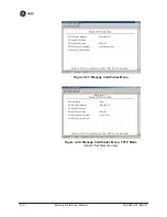
Page 108: ...ropriate files on the authentication server empty any alpha numeric string up to 16 characters User Auth Mode RADIUS Authentication algorithm PAP CHAP EAP PAP NOTE CHAP is a more secure algorithm than PAP PAP may display the login password in log files at the authentication server while CHAP will encrypt this information 3 7 4 Manage Certificates Use Certificate generation software to generate cer...

Page 109: ...100 Mercury Reference Manual 05 4446A01 Rev E Invisible place holder Figure 3 67 Manage Certificates Menu Invisible place holder Figure 3 68 Manage Certificates Menu TFTP Mode Option Set Remote only ...

Page 110: ...igure 3 70 on Page 102 Three certificate files Root CA Client and Private Key must be present in each of the Remote radios Use the commands described below to install these files into each Remote radio Certificate Type Selects one of the three certificate file types mentioned above Root CA Client Private Key Root CA Certificate Filename Specifies the software path and filename for downloading cert...

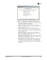
Page 111: ...unt of data sent in each TFTP packet 3 8 REDUNDANCY CONFIGURATION AP ONLY For operation in protected redundant mode an AP must be in a Pack aged P23 enclosure with a backup radio See MDS publication 05 4161A01 for details This manual is available under the Downloads tab at www GEmds com The Redundancy Configuration Menu Figure 3 71 is where you enable disable redundancy operation and define the tr...

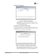
Page 112: ...igger status for Radio Events such as a loss of associated Remotes or excessive packet errors Hardware Event Triggers This selection opens a submenu Figure 3 74 on Page 105 where you can set view the trigger status for initialization hardware errors Redundancy Configuration Options This selection opens a sub menu Figure 3 75 on Page 105 where you can set the thresh old criteria for declaring an er...

Page 113: ...gers Invisible place holder Figure 3 73 Radio Event Triggers Lack of associated remotes exceeded threshold This setting deter mines whether or not a switchover occurs when a lack of asso ciated Remote units exceeds the time period set in Figure 3 76 on Page 106 enabled disabled disabled Packet Receive Errors exceeded threshold This setting determines whether or not a switchover occurs when the num...

Page 114: ...isabled Redundancy Configuration Options Menu Use this menu Figure 3 75 to set the thresholds for the Lack of Asso ciated Remotes and Packet Receive Errors Selecting either item opens a submenu where you can view or change settings Invisible place holder Figure 3 75 Redundancy Configuration Options Menu Lack of Associated Remotes Exceeded Threshold This selection opens a submenu Figure 3 76 where ...

Page 115: ...eshold Menu Lack of Remotes for Select this item to change the time setting in seconds for a lack of associated Remotes When there are no associated Remotes for a period exceeding this time a redun dancy switchover occurs 60 500 500 Packet Receive Errors Exceeded Threshold Menu Invisible place holder Figure 3 77 Packet Receive Errors Exceeded Threshold Menu Maximum Receive Errors Select this item ...

Page 116: ... Only Stream GPS to Console Used to enable disable streaming of GPS NMEA data to the console port COM1 Baud rate is 4800 baud when Stream GPS to console is enabled enabled disabled disabled GPS to Console Baud Rate The serial baud rate when GPS streaming is enabled Send GPS via UDP Used to enable disable sending GPS NMEA data to a server via UDP enabled disabled disabled GPS UDP Server IP Address ...

Page 117: ...formation GSA Polling Seconds between GSA string outputs the overall satellite data GSV Polling Seconds between GSV string outputs the detailed satellite data RMC Polling Seconds between RMC string outputs the recom mended minimum data VTG Polling Seconds between VTG string outputs the vector track and speed over ground MSS Polling Seconds between MSS string outputs the beacon receiver status info...

Page 118: ...only Uptime Display only Elapsed time since boot up Date Current date being used for the transceiver logs User set able Value lost with power failure if SNTP Simple Network Time Protocol server not accessible Time Current time of day User setable Setting HH MM SS Value lost with power failure if SNTP server not accessible Date Format Select presentation format Generic dd Mmm yyyy European dd mm yy...

Page 119: ...e information when power is removed Device Names Menu Figure 3 81 Device Names Menu Device Name Used by the transceiver as the Realm name for network login web browser only and menu headings Contact User defined appears on this screen only Location User defined appears on this screen only Description User defined appears on this screen only 3 11 PERFORMANCE INFORMATION MENU The Performance Informa...

Page 120: ...ellite fix status number of satellites being received and unit location data See Figure 3 88 on Page 116 for details Wireless Network Status Current AP association state and MAC address See Figure 3 90 on Page 118 for details Internal Radio Status Remote Only Shows connection status RF parameters and total FEC count for the unit See Figure 3 95 on Page 120 for details Performance Trend Remote Only...

Page 121: ...112 Mercury Reference Manual 05 4446A01 Rev E Invisible place holder Figure 3 83 Performance Trend Screen Invisible place holder Figure 3 84 Bridge Status Menu ...

Page 122: ...e challenge question Send File y n before the request proceeds Event Log Host Address Set display the IP address of the TFTP server any valid IP address 0 0 0 0 Event Log Filename Set display the name of the event log file on the TFTP server any valid filename eventlog txt Transfer Options A menu for configuring the TFTP transfer Syslog Server Address Use this selection to set or view the IP addre...

Page 123: ...and date from a Time Server This server is typically a standard Win dows PC server SNTP application In the absence of the SNTP services the user must manually enter time and date information at the Access Point See DEVICE INFORMATION MENU on Page 109 for SNTP server identification The manually set time and date clock relies on the unit s primary power A loss of power resets the clock to 02 Jan 200...

Page 124: ...e to transmissions corrupted by RF interference Ethernet colli sions or degradation If significant Ethernet Receive Errors are observed check the quality of your Ethernet cabling and con nectors or that you do not have cable lengths exceeding the specification limits Lost Carrier Detected This parameter reports how many times the wired Ethernet connection has lost link Clear Ethernet Statistics Re...

Page 125: ...ites orbiting the Earth twice a day only a sub set of these is visible to a receiver at a given location A good signal provides information from six to ten satellites Latitude Shows the transceiver s latitudinal location in degrees based on GPS data received from the satellites Longitude Shows the transceiver s longitudinal location in degrees based on GPS data received from the satellites Altitud...

Page 126: ...l oper ation the Remote monitors the channel for Access Point transmissions The Remote synchronizes its power timing and frequency to the Access Point then requests access to the network The Access Point and Remote check each other s authorization and authentication according to the configuration of the Device Authorization and Encryption Enable parameters and the Network Name parameter The Remote...

Page 127: ...umber of Remote transceivers currently associated with the AP Remote Database AP Only Displays a submenu where associ ated Remotes are listed in table form according to their number operational state MAC address IP address and name if assigned See Figure 3 92 on Page 119 Remote Performance Database AP Only Displays a submenu where associated Remote performance data is listed in table form Remotes ...

Page 128: ...ided in Table 4 3 on Page 152 Current AP Eth Address Displays the Ethernet MAC address of the current AP Current AP IP Address Shows the IP address of the current AP Current AP Name Displays the device name of the current AP Time Connected Shows the time at which the remote connected to the AP The Remote has been continually connected since this time Invisible place holder Figure 3 92 Remote Datab...

Page 129: ...ry Reference Manual 05 4446A01 Rev E Invisible place holder Figure 3 94 Remote Database Details Menu AP Internal Radio Status Menu Remote Only Invisible place holder Figure 3 95 Internal Radio Status Remote Only ...

Page 130: ... when they are in Hopping with Handoffs mode This allows viewing of the settings the Remote is using to connect to each AP in the AP Locations File See Frequency Control Menu on Page 67 for explanations of these items Exception The Scanning Timer parameter is unique to the screen shown in Figure 3 97 and is explained below Connection Status Indicates whether or not the Remote station has associate...

Page 131: ...es to connect to a particular AP Once this timer reaches the Max Scanning Time the Remote tries to connect to the next AP in the AP Locations File Radio Details This selection presents a screen Figure 3 98 showing key operating details of the transceiver Channel Statistics This selection presents a screen Figure 3 99 that shows signal quality on a channel by channel basis Readings are expressed in...

Page 132: ...y the radio Uncorrected FEC Count Shows the number of errored blocks that can t be corrected with FEC by the radio Invisible place holder Figure 3 99 Channel Statistics Menu 3 12 MAINTENANCE TOOLS MENU In the course of operating your network you may wish to upgrade trans ceiver firmware to take advantage of product improvements work with configuration scripts conduct ping tests of your system or r...

Page 133: ...rces See Reprogramming Menu on Page 126 Configuration Scripts Saving and importing data files contain ing unit operating parameters settings See Configuration Scripts Menu on Page 131 Ping Utility Diagnostic tool to test network connectivity See Ping Utility Menu on Page 135 Authorization Codes Alter the unit s overall capabilities by enabling the built in resources See Authorization Codes on Page...

Page 134: ... on Page 125 Auto Firmware Upgrade Brings up a submenu where you can perform tasks related to loading new firmware See Auto Firmware Upgrade Menu AP Only on Page 138 Telnet Utility A submenu for opening Telnet connections to net work devices Figure 3 103 on Page 125 Invisible place holder Figure 3 102 Firmware Versions Menu Figure 3 103 Telnet Utility Menu Host Address The IP address of the target...

Page 135: ...d firmware These notes contain important information on compatibility and any special steps needed for proper installation All units and versions have two resident images Version 1 4 4 had two mpk files one for the Access Point and one for the Remote As of version 2 1 0 there is only one mpk file which you can use with both Access Points and Remotes The transceiver has two copies of the firmware m...

Page 136: ... TFTP and USB TFTP Host Address IP address of the host computer from which to get the file Any valid IP address This same IP address is used in other screens functions reprogramming logging etc Changing it here also changes it for other screens functions Firmware Filename Name of file to be received by the TFTP server Any 40 character alphanumeric string Verify that this cor responds to the TFTP d...

Page 137: ...nsfer of firmware files See Figure 3 107 and related text descriptions Current Firmware Displays the versions of firmware images installed in the transceiver and shows whether Image 1 or Image 2 is currently active NOTE See Upgrade Procedure on Page 130 for details on setting up the TFTP server Invisible place holder Figure 3 107 Advanced Reprogramming Menu TFTP Timeout View set the time in second...

Page 138: ...tion Screen on Page 42 A TFTP server is available on the GE MDS Web site at www GEmds com Resources TechnicalSupport TIP If you do not know your computer s address on a Windows PC you can use the RUN function from the Start menu and enter winipcfg or ipconfig to determine your local PC s IP address There are several alternatives to connecting the transceiver for firmware upgrades Figure 3 108 and ...

Page 139: ... TFTP server on a PC connected either directly or via a LAN to the Ethernet port LAN of the radio Point the server towards the directory containing the firmware image file 2 Connect to the Management System by whichever means is conve nient browser or Telnet via the LAN or Terminal emulator via the COM1 port 3 Go to the MS Reprogramming Menu Main Menu Maintenance Menu Reprogramming Menu 4 Fill in ...

Page 140: ...e contains all of a radio s setable parameters that are accessible through the menu interface with a few exceptions A configuration script file is in plain text format and can be easily edited in any text program Configuration scripts can be helpful in several ways Three common uses for them are Table 3 9 Common Errors During TFTP Transfer Error Message Likely Cause Corrective Action Invalid File ...

Page 141: ... factory for technical support A technician can often spot poten tial problems by reviewing a configuration file How Configuration Files Work When a configuration script file is downloaded to a radio Retrieve File the radio executes the parameters as commands and takes the values contained in it When a configuration script file is uploaded from the radio Send it contains the current values of the ...

Page 142: ...ds for transferring files to and from the radio On firmware version 3 0 radios the options are TFTP and USB Config Filename Name of file containing this unit s configura tion profile that will be transferred to the TFTP server The con figuration information is in plain text ASCII format Any 40 character alphanumeric string May require a sub direc tory for example config mercury config txt See Conf...

Page 143: ...les are available free of charge at www GEmds com Resources TechnicalSupport The name of the specific file includes the firmware revision number represented by the x characters in the following example mercury config x_x_x txt Editing Configuration Files Once a Remote unit s operation is fine tuned use the Configuration Scripts Menu on Page 131 to save a copy of the configuration onto a PC Once th...

Page 144: ...ted from a trans ceiver do not need to be present in your customized files Some fields are read only These are designated by RO in the configuration sample file Ping Utility Menu Invisible place holder Figure 3 113 Ping Utility Menu Address to Ping Address to send a Ping Any valid IP address Count Number of Ping packets to be sent Packet Size Size of each Ping data packet bytes Device Name Should ...

Page 145: ...turn to this menu Invisible place holder Figure 3 114 Ping Results Screen Authorization Codes Invisible place holder Figure 3 115 Authorization Codes Menu Authorization Key For entering an Authorization Key into the transceiver s non volatile memory Authorized Features List of the transceiver s authorized fea tures Each item shows enabled or disabled according to the set tings allowed by the Autho...

Page 146: ...lished for your transceiver and will need to re enter them using the menu system To prevent accidental use of the command a challenge question is presented at the bottom of the screen when this choice is selected see Figure 3 116 on Page 137 To proceed enter y for yes or n for no and then press Enter You may also press the Escape key on your keyboard to exit this command without making any changes...

Page 147: ...ted remotes to Firmware for Upgrade see below Reboot Remotes Determines how a Remote behaves once it has downloaded new firmware from the AP as part of an auto upgrade When enabled the Remotes reboot to the new firmware NOTE To use the Auto Upgrade Reboot feature both the AP and Remotes must already be running version 2 1 0 or newer firm ware Firmware for Upgrade Specifies the firmware version tha...

Page 148: ... read only unless A Radio Mode is first selected and set to Test In Test Mode these items become selectable and you can set their entries using the Spacebar or with a numeric entry followed by pressing the Enter key Test Key Sets displays keying status of the radio s transmitter Use the Spacebar to view selections disabled enabled disabled Test Transmit Power Sets displays the transmitter s power ...

Page 149: ...s plays through the terminal a spectrum analyzer view of its transmit power and frequency Figure 3 120 on Page 140 Figure 3 119 Spectrum Analyzer Menu Figure 3 120 Spectrum Analyzer Display 3 13 PERFORMANCE OPTIMIZATION After checking basic radio operation you can optimize the network s performance The effectiveness of these techniques varies with the design of your system and the format of the da...

Page 150: ...g the first items checked when searching for performance gains Stronger signals allow the use of wider bandwidths and higher data speeds with fewer retries of data transmissions Time spent optimizing the antenna systems on both AP and Remote stations will often have a huge benefit to system performance Refer to INSTALLATION PLANNING on Page 163 for addi tional recommendations on antenna systems Ta...

Page 151: ...3 or 0 6 0 13 or 0 6 AP and RM must match Channel Selection User discretion User discretion Disable channels with interference AP and RM must match TDD Sync Mode GPS Required N A GPS Antennas must be connected to both AP and RM Advanced Configuration Adaptive Modulation Enabled Enabled Protection Margin 3 3 dB Hysteresis Margin 3 3 dB Data Compression Enabled Enabled Gives best throughput numbers ...

Page 152: ...h For Mobile Systems Where hand offs between APs are required AP Remote Units Notes Radio Configuration Frequency Control Frequency Mode Static Hopping Hopping w Hand offs Advanced Configuration Protection Margin 6 6 dB More channel variation in mobile so use more robust modulation with greater SNRs Channel Type Dynamic N A Less periodic ranging when Channel Type Static Network Configuration AP Lo...

Page 153: ...e application or system the radio is used in Table 3 12 Mercury Remote Transceiver Continued Performance Information Internal Radio Status Menu Name Target Value Notes Table 3 13 Mercury Access Point Performance Information Wireless Network Status Remote Performance Database Name Target Value Notes MAC ADDR MAC Address of associated Remote Must match Remote s MAC address exactly RSSI Received Sign...

Page 154: ...lly used for mobile systems with good performance Make sure there is overlap ping coverage of more than one AP to provide continuous coverage At every AP Radio review the following settings when providing service to mobile remotes TDD Sync Set to GPS Required Pattern Offset Each AP should be different Cell planning is required if there are overlaps Hop Pattern Set the same on all APs Compression d...

Page 155: ...146 Mercury Reference Manual 05 4446A01 Rev E ...

Page 156: ...rpreting the Front Panel LEDs 149 4 1 2 Troubleshooting With the Embedded Management System 150 4 1 3 Using Logged Operation Events 153 4 1 4 Alarm Conditions 154 4 1 5 Correcting Alarm Conditions 155 4 1 6 Logged Events 155 4 2 RADIO RF MEASUREMENTS 157 4 2 1 Antenna System SWR and Transmitter Power Output 157 4 2 2 Antenna Aiming For Directional Antennas 158 ...

Page 157: ...148 Mercury Reference Manual 05 4446A01 Rev E ...

Page 158: ...Do not overlook the possibility that human error is the cause of the problem With so many parameters to view and change a parameter might be incorrectly set and then that change is forgotten To help avoid these problems GE MDS recommends creating an archive of the transceiver s profile in a Configuration File when your installation is complete You can reload this file into the transceiver to resto...

Page 159: ...s Point with the same Network Name Check the Status of the unit s process of associating with the Access Point Use the Management System c Poor Antenna System Check the antenna feedline and connectors Reflected power should be less than 10 of the forward power reading SWR 2 1 or lower PWR LED is blinking a Blinking indicates that an alarm condition exists b View Current Alarms and Event Log and co...

Page 160: ...sentative c At the login prompt try the user name authcode and enter the Authorization Key for the password Remote only gets to Connecting a Check Network Name encryption and Device Auth Mode settings b Verify that the correct MAC address is listed in the Approved Remotes List of the Security Configuration Menu Remote only gets to Authenticating Check encryption settings and security mode settings...

Page 161: ...te the unit might still be operational and associated Look for the association state in the Wireless Network Status screen to determine if the unit is associated If it is look at the Error Log for possible clues If the unit is in an Alarmed state and is not associated with an Access Point then there might be a problem with the wireless network layer Call a radio technician to deal with wireless is...

Page 162: ...ul to network technicians the Radio Test Menu and the Ping Utility Use the Radio Test selection for testing RF operation Use the Ping Utility to verify communications access to pieces of equipment connected to the radio network This includes transceivers and user sup plied Ethernet devices 4 1 3 Using Logged Operation Events See PERFORMANCE INFORMATION MENU on Page 110 The transceiver s microproce...

Page 163: ... Flash Memory Temporary Informational Transient conditions or events RAM Minor Does not affect unit operation RAM Major Degraded unit performance but still capable of operation RAM Critical Prevents the unit from operating RAM Table 4 5 Alarm Conditions Alphabetical Order Alarm Condition Reported Event Log Entry SNMP Trap EVENT_BRIDGE Network Interface Error networkInterface 17 EVENT_FREQ_CAL Freq...

Page 164: ...cal Order Continued Alarm Condition Reported Event Log Entry SNMP Trap Table 4 6 Correcting Alarm Conditions Alphabetical Order Event Log Entry Generating Condition Clearing Condition or Action Bridge Down The Bridge fails to be initialized Contact factory Technical Services for assistance General System Error Internal checks suggest unit is not functioning properly Reboot the transceiver Initiali...

Page 165: ... Scanning process at a Remote Indicates that the received beacon came from an AP which is not in the Approved AP list This might be caused by some Remotes hearing multiple AP s This event is expected behavior Decryption Error Decryption OK MAJOR A decryption error is logged when an encryption phrase mismatch has occurred A mismatch is declared after five consecutive errors over a 40 second window ...

Page 166: ...ve ratio of the antenna system If the results are normal record them for comparison during future routine preventive maintenance Abnormal readings indicate possible trouble with the antenna or the transmission line and should be corrected Check the SWR of the antenna system before putting the radio into reg ular service For accurate readings a wattmeter suited to the frequency of operation is requ...

Page 167: ...and reflected power into the antenna system and calculate the SWR and power output level The output should agree with the programmed value set in the Radio Configuration Menu Radio Configuration Transmit Power 6 Turn off Radio Test Mode Maintenance Tools Menu Radio Test Test Key disabled End of procedure 4 2 2 Antenna Aiming For Directional Antennas Introduction The radio network integrity depends...

Page 168: ...rd the Wireless Packets Dropped and Received Error rates Main Menu Performance Information Packet Statistics Wireless Packet Statistics This information will be used later 3 Clear the Wireless Packets Statistics history Main Menu Performance Information Packet Statistics Wireless Packet Statistics Clear Wireless Stats 4 Read the RSSI level at the Remote Main Menu Performance Information Internal R...

Page 169: ...anual 05 4446A01 Rev E 7 If the RSSI peak results in an increase in the Wireless Packets Dropped and Received Error the antenna may be aimed at an undes ired signal source Try a different antenna orientation End of procedure ...

Page 170: ...eral Requirements 163 5 1 2 Site Selection 164 5 1 3 Terrain and Signal Strength 165 5 1 4 Antenna Feedline Selection 165 5 1 5 How Much Output Power Can be Used 169 5 1 6 Conducting a Site Survey 169 5 1 7 A Word About Radio Interference 170 5 1 8 ERP Compliance at 900 MHz 172 5 1 9 ERP Compliance at 3650 MHz 173 5 2 dBm WATTS VOLTS CONVERSION CHART174 ...

Page 171: ...162 Mercury Reference Manual 05 4446A01 Rev E ...

Page 172: ...00BaseT connections Confirm that your hub switch is capable of auto switching data rates To prevent excessive Ethernet traffic from degrading perfor mance place the transceiver in a segment or behind routers Invisible place holder Figure 5 1 Typical Fixed Remote Installation With a Directional Antenna Connect user data equipment to any compatible LAN Port Unit Dimensions Figure 5 2 on Page 164 sho...

Page 173: ...sible place holder Figure 5 3 Mounting Bracket Dimensions center to center NOTE To prevent moisture from entering the radio do not mount the radio with the cable connectors pointing up Also dress all cables to prevent moisture from running along the cables and into the radio 5 1 2 Site Selection Suitable sites should provide Protection from direct weather exposure 1 4 6 75 17 15 cm 4 5 11 43 cm TO...

Page 174: ...irable and provides the most reliable commu nications link Much depends on the minimum signal strength that can be tolerated in a given system Although the exact figure will differ from one system to another a Received Signal Strength Indication RSSI of 80 dBm or stronger will provide acceptable performance in most systems While the equipment will work at lower strength signals signals stronger th...

Page 175: ...tical polarization of the signal there fore the Remote antenna s must also be vertically polarized elements oriented perpendicular to the horizon When required horizontally polarized omnidirectional antennas are also available Contact your factory representa tive for details Invisible place holder Figure 5 4 Typical Omnidirectional Antennas At fixed Remote sites a directional Yagi antenna Figure 5...

Page 176: ... cable at 900 MHz The choice of cable depends on the required length cost con siderations and the acceptable amount of signal loss Table 5 1 lists several types of popular feedlines and indicates the signal losses in dB that result when using various lengths of cable at 900 MHz The choice of cable depends on the required length cost considerations and the acceptable amount of signal loss Table 5 1...

Page 177: ...Unacceptable Loss 7 8 inch HELIAX 0 52 dB 2 56 dB 5 12 dB Unacceptable Loss 1 1 4 inch HELIAX 0 40 dB 1 92 dB 3 8 dB 19 dB 1 5 8 inch HELIAX 0 32 dB 1 6 dB 3 2 dB 16 dB Table 5 2 Length vs Loss in Coaxial Cables at 3600 MHz Cable Type 10 Feet 3 05 m 50 Feet 15 24 m 100 Feet 30 48 m 500 Feet 152 4 m Table 5 3 Feedline Length vs Antenna Gain Required for Regulatory Compliance Antenna Gain dBd Antenn...

Page 178: ... a nominal RF power output of 29 dBm 900 model 23 dBm 3650 model this is the maximum transmitter output power allowed under FCC rules The power must be decreased from this level if the antenna system gain exceeds 6 dBi 900 model The allowable level is dependent on the antenna gain feedline loss and the transmitter output power setting NOTE In some countries the maximum allowable RF output might be...

Page 179: ...ly choose the station location configuration of radio parameters and software pro tocol techniques In general keep the following points in mind when setting up your com munications network Systems installed in rural areas are least likely to encounter interfer ence those in suburban and urban environments are more likely to be affected by other devices operating in the license free frequency band ...

Page 180: ...stined for a given remote includes when to transmit the duration of transmission and modulation selection In the event the intended Remote unit is unable to receive or interpret this information from the AP the Remote will persist in receive mode only The radio allows the installer to configure an Approved Access Point list that contains the MAC addresses of desired AP radios in the network When a...

Page 181: ...bove this is 28 dBm 3 Set the transmitter power so that it does not exceed the maximum level determined in Step 2 Main Menu Radio Configuration Transmit Power Refer to Table 5 4 which lists several antenna system gains and shows the maximum allowable power setting of the radio Note that a gain of 6 dB or less entitles you to operate the radio at full power output 30 dBm For MDS 3650 units refer al...

Page 182: ...nnas used to support operation in this band must be fixed mounted Table 5 5 Antenna Gain vs Power Setpoint 3650 MHz Antenna Gain dBi Radio Configuration Antenna Type Radio Bandwidth Radio Power Setpoint dBm 13 Omni Antenna 1 75 MHz BW 22 13 Omni Antenna 3 5 MHz BW 23 13 Omni Antenna 5 MHz BW 23 13 Omni Antenna 7 MHz BW 23 13 Omni Antenna 10 MHz BW 23 13 Omni Antenna 14 MHz BW 23 18 Panel Antenna 1...

Page 183: ...0mW 5 125 32mW 6 115 25mW 7 100 20mW 8 090 16mW 9 080 125mW 10 071 10mW 11 064 12 058 13 050 14 045 15 040 16 0355 dBm mV Po 17 31 5 18 28 5 19 25 1 20 22 5 01mW 21 20 0 22 17 9 23 15 9 24 14 1 25 12 8 26 11 5 27 10 0 28 8 9 29 8 0 30 7 1 001mW 31 6 25 32 5 8 33 5 0 34 4 5 35 4 0 36 3 5 37 3 2 38 2 85 39 2 5 40 2 25 1 W 41 2 0 42 1 8 43 1 6 44 1 4 45 1 25 46 1 18 47 1 00 48 0 90 dBm mV Po 49 0 80 ...

Page 184: ...y Reference Manual 175 6 TECHNICAL REFERENCE 6 Chapter Counter Reset Paragraph Contents 6 1 DATA INTERFACE CONNECTORS 177 6 1 1 LAN Port 177 6 1 2 COM1 Port 177 6 2 SPECIFICATIONS 178 6 3 NOTES ON SNMP 180 6 3 1 Overview 180 ...

Page 185: ...176 Mercury Reference Manual 05 4446A01 Rev E ...

Page 186: ...ss for the network to function properly To connect a PC directly to the radio s LAN port an RJ 45 to RJ 45 cross over cable is required To connect the radio to a Ethernet hub or bridge use a straight through cable The connector uses the standard Ethernet RJ 45 cables and wiring For custom made cables use the pinout information in Figure 6 1 and Table 6 1 Figure 6 1 LAN Port RJ 45 Pinout Viewed fro...

Page 187: ...hogonal Frequency Division Multiplexing OFDM 200 Carriers per Channel Available Configurations Access Point Ethernet Serial GPS Remote Ethernet Serial GPS Radio System Gain 140 dB for 1 75 MHz channel 137 dB for 3 5 MHz channel Carrier Power AP 30 to 29 dBm RM 0 to 29 dBm 900 models 23 dBm max 3650 model RF Output Impedance 50 Ohms Sensitivity and Signal Rate see Table 6 3 Table 6 3 Sensitivity an...

Page 188: ...ocols Pending contact factory for details Ethernet IEEE 802 3 Spanning Tree Bridging VLAN IGMP TCP IP DHCP ICMP UDP TCP ARP Multicast SNTP TFTP Serial Encapsulation over IP tunneling for serial async multi drop protocols including MODBUS DNP 3 DF1 BSAP GE MDS Cyber Security Suite Level 1 Encryption AES 128 Authentication 802 1x RADIUS EAP TLS PKI PAP CHAP Management SSL SSH HTTPS Management HTTP H...

Page 189: ...t obligation to notify any person of such changes 6 3 NOTES ON SNMP 6 3 1 Overview The firmware release described in this manual contains changes to the transceiver s SNMP Agent several new MIB variables and new Agent configuration options This guide reviews the changes and shows how to properly configure the Agent to take advantage of these new features SNMPv3 Support The updated SNMP Agent now s...

Page 190: ...s The following default accounts are available for the SNMP Agent enc_mdsadmin Read write account using Authentication and Encryp tion auth_mdsadmin Read write account using Authentication enc_mdsviewer Read only account using Authentication and Encryp tion auth_mdsviewer Read only account using Authentication def_mdsviewer Read only account with no Authentication or Encryp tion Context Names The ...

Page 191: ...locally then the Manager must be re con figured with any password changes in order to continue talking to the Agent Password Mode Management Changes When the password management mode is changed the active passwords used by the Agent may also change Some common scenarios are dis cussed below Common Scenarios Passwords are currently being handled by the Manager The assigned passwords are Microwave A...

Page 192: ...cpServer 42 INFORM DHCP server enabled disabled dhcpClient 43 INFORM DHCP client enabled disabled dhcpAddr 44 MINOR Obtained DHCP address timeNotSet 45 INFORM Date time not set timeByUser 46 INFORM Date time changed by user timeFromServer 47 INFORM Date time from server consoleLogin 48 MAJOR Console user login logout httpLockdown 49 MAJOR HTTP Access locked down parmChanged 50 INFORM Parameter cha...

Page 193: ...rstatus 80 MAJOR CSR read failed csrctrlsignal 81 MAJOR CSR write failed bandwidthMismatch 83 INFORM Bandwidth of AP in Locations file does not match this unit gpsSync 84 INFORM GPS synchronized lost sync gpsTddSync 85 INFORM TDD synchronized lost sync tftpClientConn 86 INFORM TFTP Connection to Client Opened Closed tftpClientError 87 MAJOR Error in TFTP Transfer to Client autoUpgrade 88 MAJOR Aut...

Page 194: ...ntenna System losses from the feedline and coaxial connectors for example are subtracted from this figure to calculate the total antenna system gain AP See Access Point Association Condition in which the frequency hopping pattern of the Remote is synchronized with the Access Point station and the Remote is ready to pass traffic Authorization Key Alphanumeric string code that is used to enable addi...

Page 195: ...ignal levels Fre quently used to express the gain or loss of a system Delimiter A flag that marks the beginning and end of a data packet Device Mode The operating mode role of a transceiver Access Point or Remote in a wireless network DHCP Dynamic Host Configuration Protocol An Internet stan dard that allows a client i e any computer or network device to obtain an IP address from a server on the n...

Page 196: ...at will be anticipated under most conditions Provides an allowance for reduced signal strength due to multipath slight antenna movement or changing atmospheric losses A fade margin of 15 to 20 dB is usually sufficient in most systems Fragmentation A technique used for breaking a large message down into smaller parts so it can be accommodated by a less capable media Frame A segment of data that adh...

Page 197: ...cking The 802 1X port device denies access to the network until the client device has authenticated itself Image File Data file that contains the operating system and other essential resources for the basic operation of the radio s CPU LAN Local Area Network Latency The delay usually expressed in milliseconds between when data is applied at the transmit port at one radio until it appears at the re...

Page 198: ...st reachability of a network device either over a wired or wireless net work PKI Private Key Infrastructure A set of policies and technologies needed to create store and distribute Public Key Certificates used to protect the security of network communications Point to Multipoint System A radio communications network or system designed with a central control station that exchanges data with a numbe...

Page 199: ...Terminal Unit See RTU RFI Radio Frequency Interference Roaming A station s ability to automatically switch its wireless con nection between various access points APs as the need arises A station may roam from one AP to another because the signal strength or quality of the current AP has degraded below what another AP can provide Roaming may also be employed in conjunction with Portability where th...

Page 200: ...tenna system As a general guideline reflected power should not exceed 10 of the forward power 2 1 SWR TCP Transmission Control Protocol TFTP Trivial File Transfer Protocol Trap Manager Software that collects SNMP traps for display or log ging of events UDP User Datagram Protocol UTP Unshielded Twisted Pair VLAN Virtual Local Area Network A network configuration employing IEEE 802 1Q tagging which ...

Page 201: ...192 Mercury Reference Manual 05 4446A01 Rev E ...
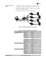
Page 202: ...application IP to Serial 83 Mixed Modes 87 Point to Multipoint Serial to Serial 84 Point to Point Serial to Serial 83 Serial Port 87 approvals agency 180 Approved Remotes 96 ARQ 74 Block Lifetime 74 Block Size 74 Receiver Delay 74 Transmitter Delay 74 Window Size 74 Associated 152 Remotes 43 118 association defined 185 process 117 attenuation 24 Auth Server Address 99 Port 99 Shared Secret 99 Auth...

Page 203: ...tion Status 43 119 121 143 connectionware 145 connector descriptions 177 Ethernet 10 console baud rate 76 109 Contact 110 context names 181 Corrected FEC Count 123 144 cost of deployment 12 Count 135 CRC Cyclic Redundancy Check defined 185 CSMA CA defined 185 CD defined 185 Current Alarms 113 Current AP 70 Eth Address 119 IP Address 119 Name 119 121 144 Current IP Address 42 50 53 Gateway 50 53 Ne...

Page 204: ...7 file certificate 97 MIB 33 Filename 127 filtering enable 57 firmware automatic upgrade 125 current 128 filename 130 for Upgrade 138 installing 129 upgrade 130 138 version 43 125 Flow Control hardware defined 187 Force Switchover 103 Fragmentation defined 187 frame defined 187 duration 70 Free Run 24 27 29 frequency control 66 hopping defined 187 mode 26 68 offset RX 144 TX 144 fuse 19 G gain ant...

Page 205: ... 49 50 53 Configuration 46 current address 50 53 gateway 50 netmask 50 gateway 53 134 netmask 53 Protocol 80 static address 49 netmask 49 tunneling 76 K KEY command 157 transmitter for antenna SWR check 157 L Lack of Associated Remotes Exceeded Threshold 104 105 Menu 106 Lack of Remotes for 106 LAN defined 188 wireless 10 12 LAT 63 Latency defined 188 Latitude 116 LED COM1 30 LAN 29 38 39 150 LINK...

Page 206: ...vision Multiplexing 4 Outgoing Connection s Inactivity Timeout 81 P P23 8 Packet defined 189 Receive Errors Exceeded Threshold 104 106 Menu 106 Size 135 Statistics 111 114 153 packets dropped 115 153 received 115 sent 115 password admin 95 guest 95 Pattern Offset 145 PC connection to transceiver 25 host 86 peer to peer communications 10 Performance Information 45 Trend 111 PING 23 30 123 170 addre...

Page 207: ...tabase 118 radio defined 190 Standard 6 Terminal Unit 13 defined 190 view approved 97 Repeater 14 antennas 15 Network Name 15 Using the AP as a Store and Forward Packet Repeater 15 Using two transceivers to form a repeater station 14 Reprogramming 124 Menu 126 Reset to Factory Defaults 124 137 Retries 153 Retrieve Certificate 101 File 128 134 Retry errors 153 RF bandwidth 26 69 Output Power 26 pow...

Page 208: ...optimization 157 Syslog Server Address 113 system gain antenna defined 185 T tabletop network 23 TCP 76 77 86 client 77 defined 191 server 77 TDD Sync Mode 15 70 145 TDD Sync 26 Telnet 36 76 83 98 Access 94 session 38 Utility 125 Test Burst Percentage 139 Channel 139 Key 139 RF Bandwidth 139 Status 139 Transmit Power 139 TFTP Block Size 102 defined 191 Host Address 62 101 127 130 133 134 Timeout 1...

Page 209: ...ed Remotes 97 Current Settings 78 Event Log 113 Menu 114 VLAN 48 191 data 48 49 Ethport Mode 49 ID 49 management 48 49 Status 46 47 49 Voice over IP 4 13 VoIP 4 13 volts dBm watts conversion 174 W watts dBm volts conversion 174 Web browser 36 76 session 39 Wireless LAN 10 Network Status 111 Menu 117 Security 93 Menu 95 wizard serial configuration 77 Write community String 59 Y Yagi antenna 166 ...

Page 210: ...helps expedite the repair so that the equipment can be repaired and returned to you as quickly as possible Please be sure to include the SRO number on the outside of the shipping box and on any corre spondence relating to the repair No equipment will be accepted for repair without an SRO number SRO numbers are issued online at www GEmds com support product sro Your number will be issued immediatel...

Page 211: ...GE MDS LLC Rochester NY 14620 General Business 1 585 242 9600 FAX 1 585 242 9620 Web www GEmds com 175 Science Parkway ...

Reviews: