CHAPTER 2: INSTALLATION
ELECTRICAL INSTALLATION
345 TRANSFORMER PROTECTION SYSTEM – INSTRUCTION MANUAL
2–17
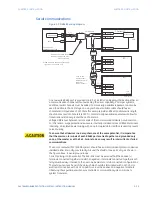
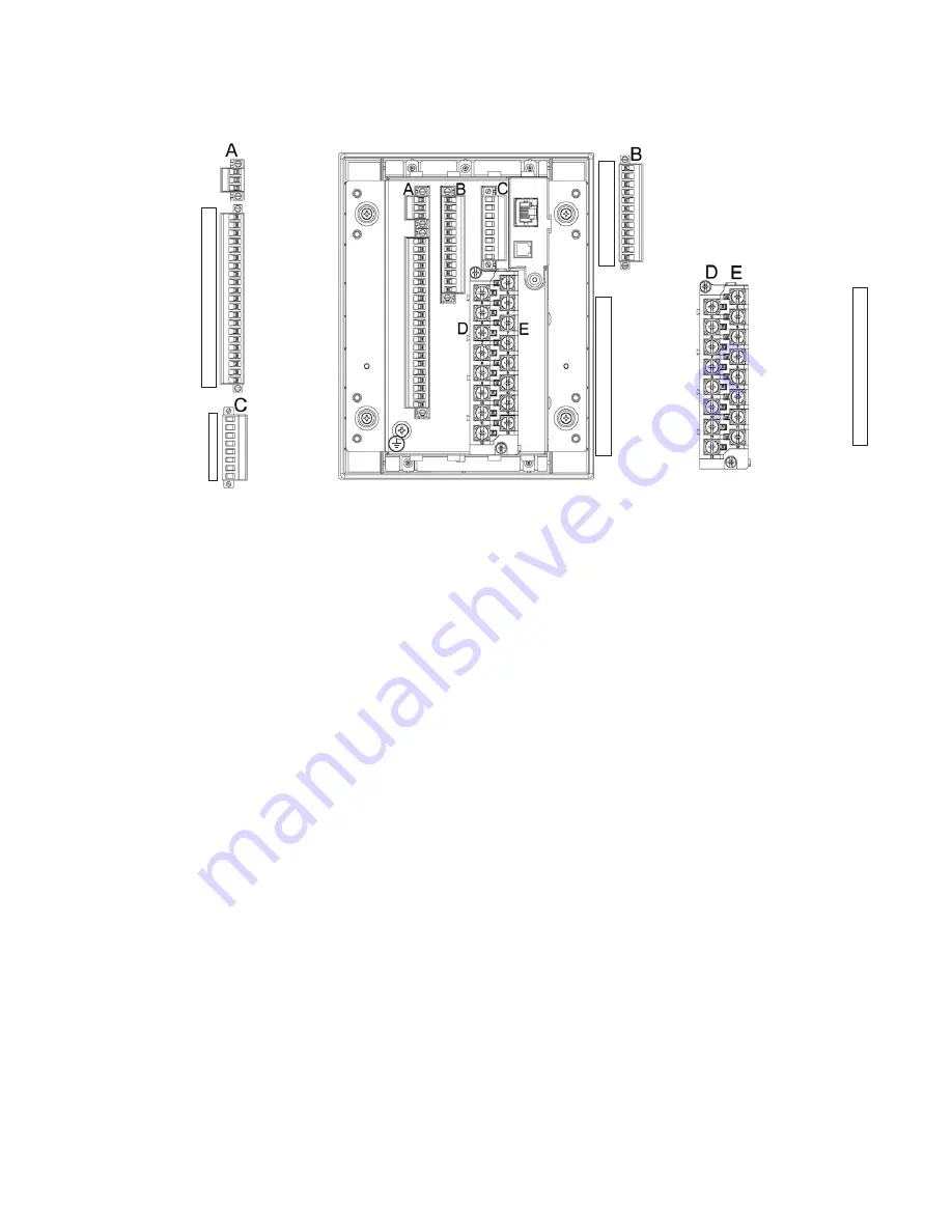
Figure 2-20: Terminal Identification - Non-drawout
Wire range
Use the following guideline when selecting wires or lugs to connect to terminal blocks
A,B,C,D,E (Drawout case design), and terminal blocks D,E (Non-drawout case design):
•
12 AWG to 22 AWG (3.3 mm
2
to 0.3 mm
2
): Single wire termination with/without
9.53 mm (0.375”) maximum diameter ring terminals.
•
14 AWG to 22 AWG (2.1 mm
2
to 0.3 mm
2
): Multiple wire termination with matching
wire sizes and stranding. Two wires maximum per circuit.
•
14 AWG to 22 AWG (2.1 mm
2
to 0.3 mm
2
): Multiple wire termination with 9.53 mm
(0.375”) maximum diameter ring terminals. Two ring terminals maximum per circuit.
•
Suggested wiring screw tightening torque, tighten to 12 in-lb (1.35 N-m).
•
The uncovered communications cable shield connected to the common terminal
should not exceed 1” (2.5 cm) for proper EMC shielding of the communications cable.
INPUT 1
INPUT 2
INPUT 3
INPUT 4
INPUT 5
INPUT 6
INPUT 7
INPUT 8
INPUT 9
INPUT 10
INPUT COM
CHASSIS GND
1
2
3
4
5
6
7
8
9
10
11
12
W1 PHASE A CT
W1 PHASE B CT
W1 PHASE C CT
W1 GND CT
W2 PHASE A CT
W2 PHASE B CT
W2 PHASE C CT
W2 GND VT
W1 PHASE A CT
W1 PHASE B CT
W1 PHASE C CT
W1 GND CT
W2 PHASE A CT
W2 PHASE B CT
W2 PHASE C CT
W2 GND VT
■
■
■
■
■
■
■
■
5
6
7
8
9
10
11
12
POWER SUPPLY -
POWER
CHASSIS GND
W1 TRIP N/O
W1 TRIP OPTV
W2 TRIP COM
AUX 3 N/C
AUX 3 N/O
AUX 4 COM
AUX 5 N/C
AUX 5 N/O
AUX 6 COM
CRIT FAIL N/C
CRIT FAIL N/O
W1 TRIP COM
W2 TRIP N/O
W2 TRIP OPTV
AUX 3 COM
AUX 4 N/C
AUX 4 N/O
AUX 5 COM
AUX 6 N/C
AUX 6 N/O
CRIT FAIL COM
1
2
3
4
5
6
7
8
9
10
11
12
13
14
15
16
17
18
19
20
21
IRIG-B +
IRIG-B -
RS485 +
RS485 -
RS485 COM
CHASSIS GND
RESERVED
RESERVED
1
2
3
4
5
6
7
8
5
6
7
8
9
10
11
12
Summary of Contents for 345
Page 89: ...CHAPTER 3 INTERFACES SOFTWARE SETUP 345 TRANSFORMER PROTECTION SYSTEM INSTRUCTION MANUAL 3 35 ...
Page 92: ...3 38 345 TRANSFORMER PROTECTION SYSTEM INSTRUCTION MANUAL SOFTWARE SETUP CHAPTER 3 INTERFACES ...
Page 254: ...A 8 345 TRANSFORMER PROTECTION SYSTEM INSTRUCTION MANUAL CHANGE NOTES ...


