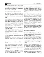
APPENDIX B
B-5
ACTION
REFERENCE
MALFUNCTION
5. Perform the calibration mode relay test to verify
the operation of the assigned relay(s).
1. Check that the circuit connected to the Analog out
terminal and verify that no external voltage larger
than 30V ( DC or peak to peak AC )is present.
2. Verify the requested parameter is as intended by
viewing the analog output parameter message.
a) If the selected analog output parameter is feeder
frequency, phase or ground fault current or phase
voltage these values can be read from the relevant
page in the actual values mode. Verify from the
actual values that the parameter does not have a
value of zero, in which case no output will be
present.
b) If the selected analog output parameter is external
analog select, then the analog output is determined
by the input presented at the Analog Select termi-
nals. Refer to the Instruction manual to determine
the correct inputs to these terminals for any output.
1. Check MTM communication setpoint.
2. Check MTM default power switch. The MTM can
be powered from the PTs or line. The default is
line; the switch must be toggled for PT.
1. Check and verify the secondary voltages meas-
ured at 565/575 terminals 35, 36, 37 and 38.
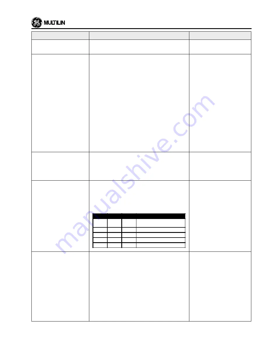
2. Check the wiring. See the following table for com-
monly made errors. The correct nominal voltage
in each example should be 4.16 kV.
1. Check and verify that all the required phases are
below the programmed threshold.
2. For a Wye configuration, one phase must be
below the programmed threshold for an alarm
while two phases are required to be below the
threshold for a trip. The same is true for an Open
Delta connection, but with the additional criteria
that the phases must be measured (V
AB
& V
BC
)
and not calculated (V
AC
).
18. Analog output param-
eter not operating.
19. No MTM communication.
20. Poor Open Delta voltage
readings.
21. Undervoltage Trip feature
does not work.
Setpoints page 8.
Relay wiring diagram.
Setpoints page 6.
Instruction Manual section 5.
Setpoints page 6.
Setpoint page 4.
See MTM power selection dia-
gram.
Setpoints page 9.
V
AB
V
BC
V
CA
PROBLEM
4.16 kV
0.00 kV
4.16 kV VT connection setpoint
programmed as Wye or Delta/Wye
2.50 kV
2.50 kV
4.16 kV V
B
to V
N
jumper missing at relay
4.16 kV
4.16 kV
7.00 kV V
A
swapped with V
B
at one PT.
4.16 kV
4.16 kV
7.00 kV V
B
swapped with V
C
at one PT.
4.16 kV
4.16 kV
3.90 kV V
A
swapped with V
C
at one relay.
Summary of Contents for 565
Page 6: ...INSTALLATION 2 2 Figure 2 1 Mounting Details ...
Page 7: ...INSTALLATION 2 3 Figure 2 2 Mounting Arrangement with Relay Collar ...
Page 12: ...INSTALLATION 2 8 Figure 2 5 565 Relay Typical Wiring ...
Page 13: ...INSTALLATION 2 9 Figure 2 6 Voltage Sensing Wire ...
Page 14: ...INSTALLATION 2 10 Figure 2 7A 565 with MTM CT and Open Delta VT Typical Wiring ...
Page 15: ...INSTALLATION 2 11 Figure 2 7B 565 with MTM CT and Wye VT Typical Wiring ...
Page 16: ...INSTALLATION 2 12 Figure 2 8A Open Delta VT and CT MTM Typical Wiring ...
Page 17: ...INSTALLATION 2 13 Figure 2 8B Wye VT and CT MTM Typical Wiring ...
Page 18: ...INSTALLATION 2 14 Figure 2 9 MTM Mounting Dimensions ...
Page 19: ...INSTALLATION 2 15 Figure 2 10 565 Rear Panel Layout ...
Page 20: ......
Page 23: ...DISPLAY AND KEYBOARD 3 3 Figure 4 1 565 Relay Front Panel ...
Page 28: ......
Page 132: ......
Page 142: ...CURVE INFORMATION ANDTABLES 7 10 Figure 7 9 IEC A Curves ...
Page 143: ...CURVE INFORMATION ANDTABLES 7 11 Figure 7 10 IEC B Curves ...
Page 144: ...CURVE INFORMATION ANDTABLES 7 12 Figure 7 11 IEC C Curves ...
Page 176: ...RELAYTESTING 8 2 Figure 8 1 Secondary Injection Test Setup ...
Page 180: ......
Page 184: ......
Page 192: ...APPENDIX C C 2 Figure C1 System Controller Block Diagram 1 2 ...
Page 193: ...APPENDIX C C 3 Figure C2 System Controller Block Diagram 2 2 ...
Page 194: ......
Page 198: ......


