background image

2–42

745 TRANSFORMER PROTECTION SYSTEM – COMMUNICATIONS GUIDE

MODBUS PROTOCOL

CHAPTER 2: MODBUS PROTOCOL

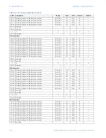
1212

FlexCurve C delay at 1.10 

×

 pickup

0 to 65000

1

ms

F1

0 ms

1213

FlexCurve C delay at 1.20 

×

 pickup

0 to 65000

1

ms

F1

0 ms

1214

FlexCurve C delay at 1.30 

×

 pickup

0 to 65000

1

ms

F1

0 ms

1215

FlexCurve C delay at 1.40 

×

 pickup

0 to 65000

1

ms

F1

0 ms

1216

FlexCurve C delay at 1.50 

×

 pickup

0 to 65000

1

ms

F1

0 ms

1217

FlexCurve C delay at 1.60 

×

 pickup

0 to 65000

1

ms

F1

0 ms

1218

FlexCurve C delay at 1.70 

×

 pickup

0 to 65000

1

ms

F1

0 ms

1219

FlexCurve C delay at 1.80 

×

 pickup

0 to 65000

1

ms

F1

0 ms

121A

FlexCurve C delay at 1.90 

×

 pickup

0 to 65000

1

ms

F1

0 ms

121B

FlexCurve C delay at 2.00 

×

 pickup

0 to 65000

1

ms

F1

0 ms

121C

FlexCurve C delay at 2.10 

×

 pickup

0 to 65000

1

ms

F1

0 ms

121D

FlexCurve C delay at 2.20 

×

 pickup

0 to 65000

1

ms

F1

0 ms

121E

FlexCurve C delay at 2.30 

×

 pickup

0 to 65000

1

ms

F1

0 ms

121F

FlexCurve C delay at 2.40 

×

 pickup

0 to 65000

1

ms

F1

0 ms

1220

FlexCurve C delay at 2.50 

×

 pickup

0 to 65000

1

ms

F1

0 ms

1221

FlexCurve C delay at 2.60 

×

 pickup

0 to 65000

1

ms

F1

0 ms

1222

FlexCurve C delay at 2.70 

×

 pickup

0 to 65000

1

ms

F1

0 ms

1223

FlexCurve C delay at 2.80 

×

 pickup

0 to 65000

1

ms

F1

0 ms

1224

FlexCurve C delay at 2.90 

×

 pickup

0 to 65000

1

ms

F1

0 ms

1225

FlexCurve C delay at 3.00 

×

 pickup

0 to 65000

1

ms

F1

0 ms

1226

FlexCurve C delay at 3.10 

×

 pickup

0 to 65000

1

ms

F1

0 ms

1227

FlexCurve C delay at 3.20 

×

 pickup

0 to 65000

1

ms

F1

0 ms

1228

FlexCurve C delay at 3.30 

×

 pickup

0 to 65000

1

ms

F1

0 ms

1229

FlexCurve C delay at 3.40 

×

 pickup

0 to 65000

1

ms

F1

0 ms

122A

FlexCurve C delay at 3.50 

×

 pickup

0 to 65000

1

ms

F1

0 ms

122B

FlexCurve C delay at 3.60 

×

 pickup

0 to 65000

1

ms

F1

0 ms

122C

FlexCurve C delay at 3.70 

×

 pickup

0 to 65000

1

ms

F1

0 ms

122D

FlexCurve C delay at 3.80 

×

 pickup

0 to 65000

1

ms

F1

0 ms

122E

FlexCurve C delay at 3.90 

×

 pickup

0 to 65000

1

ms

F1

0 ms

122F

FlexCurve C delay at 4.00 

×

 pickup

0 to 65000

1

ms

F1

0 ms

1230

FlexCurve C delay at 4.10 

×

 pickup

0 to 65000

1

ms

F1

0 ms

1231

FlexCurve C delay at 4.20 

×

 pickup

0 to 65000

1

ms

F1

0 ms

1232

FlexCurve C delay at 4.30 

×

 pickup

0 to 65000

1

ms

F1

0 ms

1233

FlexCurve C delay at 4.40 

×

 pickup

0 to 65000

1

ms

F1

0 ms

1234

FlexCurve C delay at 4.50 

×

 pickup

0 to 65000

1

ms

F1

0 ms

1235

FlexCurve C delay at 4.60 

×

 pickup

0 to 65000

1

ms

F1

0 ms

1236

FlexCurve C delay at 4.70 

×

 pickup

0 to 65000

1

ms

F1

0 ms

1237

FlexCurve C delay at 4.80 

×

 pickup

0 to 65000

1

ms

F1

0 ms

1238

FlexCurve C delay at 4.90 

×

 pickup

0 to 65000

1

ms

F1

0 ms

1239

FlexCurve C delay at 5.00 

×

 pickup

0 to 65000

1

ms

F1

0 ms

123A

FlexCurve C delay at 5.10 

×

 pickup

0 to 65000

1

ms

F1

0 ms

123B

FlexCurve C delay at 5.20 

×

 pickup

0 to 65000

1

ms

F1

0 ms

123C

FlexCurve C delay at 5.30 

×

 pickup

0 to 65000

1

ms

F1

0 ms

123D

FlexCurve C delay at 5.40 

×

 pickup

0 to 65000

1

ms

F1

0 ms

123E

FlexCurve C delay at 5.50 

×

 pickup

0 to 65000

1

ms

F1

0 ms

123F

FlexCurve C delay at 5.60 

×

 pickup

0 to 65000

1

ms

F1

0 ms

1240

FlexCurve C delay at 5.70 

×

 pickup

0 to 65000

1

ms

F1

0 ms

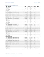
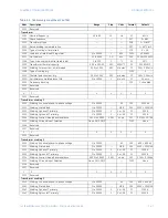
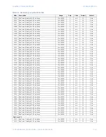
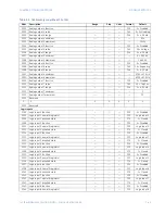
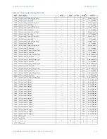
Table 2–4: 745 memory map (Sheet 30 of 56)

Addr

Description

Range

Step

Units

Format

Default

Summary of Contents for 745

Page 1: ...eet Markham Ontario Canada L6C 0M1 Tel 1 905 927 7070 Fax 1 905 927 5098 Internet http www gegridsolutions com 745 revision 5 2x Manual Part Number 1601 0162 A9 GE publication code GEK 106636H 745 Transformer Protection System Communications Guide GE Grid Solutions 1601 0162 A9 ...

Page 2: ...in The contents of this manual are the property of GE Multilin This documentation is furnished on license and may not be reproduced in whole or in part without the permission of GE Multilin The content of this manual is for informational use only and is subject to change without notice Part numbers contained in this manual are subject to change without notice and should therefore be verified by GE...

Page 3: ...MODBUS FUNCTIONS 4 READ ACTUAL VALUES OR SETPOINTS 4 EXECUTE OPERATION 5 STORE SINGLE SETPOINT 6 STORE MULTIPLE SETPOINTS 7 EXCEPTION RESPONSES 7 READING THE EVENT RECORDER 8 READING TRACE MEMORY 8 ACCESSING DATA VIA THE USER MAP 9 FUNCTION CODE SUBSTITUTIONS 11 MODBUS MEMORY MAP 12 MEMORY MAP ORGANIZATION 12 745 MEMORY MAP 13 MEMORY MAP DATA FORMATS 69 3 DNP PROTOCOL OVERVIEW 1 DEVICE PROFILE DOC...

Page 4: ...TOC II 745 TRANSFORMER PROTECTION SYSTEM COMMUNICATIONS GUIDE TABLE OF CONTENTS ...

Page 5: ...elay functions A complete description of the services available via DNP may be found in the Device Profile Document which is included in this chapter DNP is a complex protocol As a consequence it is not possible within the scope of this manual to provide a description of the protocol s operation in anything approaching the detail required to understand how to use it to communicate with the relay I...

Page 6: ...will not act on a request from a master if the address in the request does not match the relay s slave address unless the address is the broadcast address see below A single setpoint selects the slave address used for all ports with the exception that for the front panel port the relay will accept any address when the Modbus protocol is used The slave address is otherwise the same regardless of th...

Page 7: ...otocol exists in two versions Remote Terminal Unit RTU binary and ASCII Only the RTU version is supported by the 745 Monitoring programming and control functions are possible using read and write register commands Additional information on the Modbus protocol can be found on the Modbus website at http www modbus org Electrical interface The hardware or electrical interface is any of the following ...

Page 8: ...y message the slave address represents the address of the slave to which the request is being sent In a slave response message the slave address is a confirmation representing the address of the slave that is sending the response A master query message with a slave address of 0 indicates a broadcast command All slaves on the communication link will take action based on the message but none will re...

Page 9: ... to avoid the slave device performing any incorrect operation The CRC 16 calculation is an industry standard method used for error detection CRC 16 algorithm Once the following algorithm is completed the working register A will contain the CRC value to be transmitted Note that this algorithm requires the characteristic polynomial to be reverse bit ordered The most significant bit of the characteri...

Page 10: ...utions on page 2 11 for details Read actual values or setpoints Modbus implementation Read holding registers GE Multilin implementation Read actual values or setpoints Since some PLC Modbus implementations only support one of function codes 03h and 04h the 745 interpretation allows either code to be used for reading one or more consecutive setpoints or actual values The data starting address deter...

Page 11: ... 03 3 register values 6 bytes total CRC low high 06 E3 computed cyclic redundancy check Slave response Example Description Slave address 11 response message from slave 11 Function code 03 read register values Byte count 06 3 register values 6 bytes total Data 1 high low 02 2B register value in address 0200 022B Data 2 high low 00 00 register value in address 0201 0000 Data 3 high low 00 64 registe...

Page 12: ...the same function as the CLEAR MAX DEMAND DATA actual values command 0004 Clear event recorder data Performs the same function as the CLEAR EVENT RECORD DATA actual values command 0005 Clear loss of life data Performs the same function as the CLEAR LOSS OF LIFE DATA setpoints command 0006 Clear trace memory Clears all trace memory buffers and sets the Total number of trace triggers register to zer...

Page 13: ...bytes of data Data 1 high low 00 C8 data for address 1100 00C8 Data 2 high low 00 01 data for address 1101 0001 CRC low high 27 01 CRC computed by master Slave response Example Description Slave address 11 response message from slave 11 Function code 10 store multiple setpoint values Data starting address high low 11 00 data starting at address 1100 Number of setpoints high low 00 02 2 setpoint va...

Page 14: ...w reads a value of 27 from the register when previously the value was 24 which means that three new events have occurred during the last minute The SCADA system writes a value of 25 to the event record selector index register It then reads the data for event number 25 from the event recorder data registers and stores the data to permanent memory for retrieval by an operator The SCADA system now wr...

Page 15: ...ta registers and stores the data to memory for retrieval by an operator The SCADA system now writes the value 1 to the trace channel selector index and then reads the waveform data for Winding 1 phase B current The SCADA system continues by writing all other channel numbers to the trace channel selector index each time reading the waveform data until all channels for buffer 6 have been read All th...

Page 16: ...oint values Data starting address high low 01 80 data starting at address 0180 Number of setpoints high low 00 06 6 setpoint values 12 bytes total Byte count 0C 12 bytes of data Data 1 high low 02 00 0200 Relay status Data 2 high low 02 10 0210 W3 Phase time overcurrent flag Data 3 high low 03 00 0300 W1 ΦA 4th harmonic content Data 4 high low 03 01 0301 W1 ΦB 4th harmonic content Data 5 high low ...

Page 17: ...ontent 1 ƒ0 Data 6 high low 00 1E Percent differential pickup 0 30 Id CRC low high 80 F1 CRC computed by slave Master query message Example Description Slave address 11 query message for slave 11 Function code 06 store single setpoint values Data starting address high low 01 85 data starting at address 0185 Data high low 00 14 0014 0 30 Id CRC low high 9B 40 CRC computed by master Slave response E...

Page 18: ...e 11 Function code 10 store multiple setpoints substituted for function code 06h Data starting address high low 11 00 data starting at address 1100 Number of setpoints high low 00 01 1 setpoint values 2 bytes total Byte count 02 2 bytes of data Data high low 00 C8 data for address 1100 00C8 CRC low high 6B 07 CRC computed by master Slave response Example Description Slave address 11 response messa...

Page 19: ...s F15 0021 Modify passcode F33 0022 Reserved 0023 Reserved 007F Reserved Commands Addresses 0080 to 00FF Read Write Commands 0080 Command operation code F19 0081 Passcode access 4 registers Note From version 5 23 onward relay response to read request is 00000000 F33 00000000 0085 Change passcode 4 registers Note From version 5 23 onward relay response to read request is 00000000 F33 00000000 0089 ...

Page 20: ...e 2 0102 User map value 3 0103 User map value 4 0104 User map value 5 0105 User map value 6 0106 User map value 7 0107 User map value 8 0108 User map value 9 0109 User map value 10 010A User map value 11 010B User map value 12 010C User map value 13 010D User map value 14 010E User map value 15 010F User map value 16 0110 User map value 17 0111 User map value 18 0112 User map value 19 0113 User ma...

Page 21: ...e 49 0131 User map value 50 0132 User map value 51 0133 User map value 52 0134 User map value 53 0135 User map value 54 0136 User map value 55 0137 User map value 56 0138 User map value 57 0139 User map value 58 013A User map value 59 013B User map value 60 013C User map value 61 013D User map value 62 013E User map value 63 013F User map value 64 0140 User map value 65 0141 User map value 66 0142...

Page 22: ... User map value 96 0160 User map value 97 0161 User map value 98 0162 User map value 99 0163 User map value 100 0164 User map value 101 0165 User map value 102 0166 User map value 103 0167 User map value 104 0168 User map value 105 0169 User map value 106 016A User map value 107 016B User map value 108 016C User map value 109 016D User map value 110 016E User map value 111 016F User map value 112 ...

Page 23: ...User map address 22 0000 to FFFF 0001 hex F1 0000 hex 0196 User map address 23 0000 to FFFF 0001 hex F1 0000 hex 0197 User map address 24 0000 to FFFF 0001 hex F1 0000 hex 0198 User map address 25 0000 to FFFF 0001 hex F1 0000 hex 0199 User map address 26 0000 to FFFF 0001 hex F1 0000 hex 019A User map address 27 0000 to FFFF 0001 hex F1 0000 hex 019B User map address 28 0000 to FFFF 0001 hex F1 0...

Page 24: ...001 hex F1 0000 hex 01C4 User map address 69 0000 to FFFF 0001 hex F1 0000 hex 01C5 User map address 70 0000 to FFFF 0001 hex F1 0000 hex 01C6 User map address 71 0000 to FFFF 0001 hex F1 0000 hex 01C7 User map address 72 0000 to FFFF 0001 hex F1 0000 hex 01C8 User map address 73 0000 to FFFF 0001 hex F1 0000 hex 01C9 User map address 74 0000 to FFFF 0001 hex F1 0000 hex 01CA User map address 75 0...

Page 25: ...0 hex 01ED User map address 110 0000 to FFFF 0001 hex F1 0000 hex 01EE User map address 111 0000 to FFFF 0001 hex F1 0000 hex 01EF User map address 112 0000 to FFFF 0001 hex F1 0000 hex 01F0 User map address 113 0000 to FFFF 0001 hex F1 0000 hex 01F1 User map address 114 0000 to FFFF 0001 hex F1 0000 hex 01F2 User map address 115 0000 to FFFF 0001 hex F1 0000 hex 01F3 User map address 116 0000 to ...

Page 26: ...rent flag F52 0222 Winding 3 ground time overcurrent flag F52 0223 Winding 1 ground instantaneous overcurrent 1 flag F52 0224 Winding 2 ground instantaneous overcurrent 1 flag F52 0225 Winding 3 ground instantaneous overcurrent 1 flag F52 0226 Winding 1 ground instantaneous overcurrent 2 flag F52 0227 Winding 2 ground instantaneous overcurrent 2 flag F52 0228 Winding 3 ground instantaneous overcur...

Page 27: ...52 024D Aging factor limit flag F52 024E Tap changer failure flag F52 024F Reserved 0250 Reserved 025F Reserved Input output flags 0260 Logic input assert flags F56 0261 Virtual input assert flags F56 0262 Output relay operate flags F57 0263 Virtual output operate flags F59 0264 Timer operate flags F61 0265 Reserved 0266 Reserved 027F Reserved Winding 1 current 0280 Winding 1 phase A current magni...

Page 28: ...0 02A1 Winding 3 phase A current angle 0 to 359 1 Lag F1 02A2 Winding 3 phase B current magnitude A F80 02A3 Winding 3 phase B current angle 0 to 359 1 Lag F1 02A4 Winding 3 phase C current magnitude A F80 02A5 Winding 3 phase C current angle 0 to 359 1 Lag F1 02A6 Winding 3 neutral current magnitude A F80 02A7 Winding 3 neutral current angle 0 to 359 1 Lag F1 02A8 Winding 3 ground current magnitu...

Page 29: ...itude 0 00 to 655 35 0 01 x CT F3 02D5 Phase C differential current angle 0 to 359 1 Lag F1 Restraint current 02D6 Phase A restraint current 0 00 to 655 35 0 01 x CT F3 02D7 Phase B restraint current 0 00 to 655 35 0 01 x CT F3 02D8 Phase C restraint current 0 00 to 655 35 0 01 x CT F3 Ground differential current 02D9 Winding 1 ground differential current 0 000 to 65 535 0 001 x CT F53 02DA Windin...

Page 30: ...ntent 0 0 to 99 9 0 1 ƒo F2 0305 Winding 2 phase C 4th harmonic content 0 0 to 99 9 0 1 ƒo F2 0306 Winding 3 phase A 4th harmonic content 0 0 to 99 9 0 1 ƒo F2 0307 Winding 3 phase B 4th harmonic content 0 0 to 99 9 0 1 ƒo F2 0308 Winding 3 phase C 4th harmonic content 0 0 to 99 9 0 1 ƒo F2 0309 Reserved 030A Reserved 030F Reserved 5th harmonic 0310 Winding 1 phase A 5th harmonic content 0 0 to 99...

Page 31: ...9 9 0 1 ƒo F2 0339 Reserved 033A Reserved 033F Reserved 8th harmonic 0340 Winding 1 phase A 8th harmonic content 0 0 to 99 9 0 1 ƒo F2 0341 Winding 1 phase B 8th harmonic content 0 0 to 99 9 0 1 ƒo F2 0342 Winding 1 phase C 8th harmonic content 0 0 to 99 9 0 1 ƒo F2 0343 Winding 2 phase A 8th harmonic content 0 0 to 99 9 0 1 ƒo F2 0344 Winding 2 phase B 8th harmonic content 0 0 to 99 9 0 1 ƒo F2 0...

Page 32: ... C 11th harmonic content 0 0 to 99 9 0 1 ƒo F2 0373 Winding 2 phase A 11th harmonic content 0 0 to 99 9 0 1 ƒo F2 0374 Winding 2 phase B 11th harmonic content 0 0 to 99 9 0 1 ƒo F2 0375 Winding 2 phase C 11th harmonic content 0 0 to 99 9 0 1 ƒo F2 0376 Winding 3 phase A 11th harmonic content 0 0 to 99 9 0 1 ƒo F2 0377 Winding 3 phase B 11th harmonic content 0 0 to 99 9 0 1 ƒo F2 0378 Winding 3 pha...

Page 33: ...tent 0 0 to 99 9 0 1 ƒo F2 03A6 Winding 3 phase A 14th harmonic content 0 0 to 99 9 0 1 ƒo F2 03A7 Winding 3 phase B 14th harmonic content 0 0 to 99 9 0 1 ƒo F2 03A8 Winding 3 phase C 14th harmonic content 0 0 to 99 9 0 1 ƒo F2 03A9 Reserved 03AA Reserved 03AF Reserved 15th harmonic 03B0 Winding 1 phase A 15th harmonic content 0 0 to 99 9 0 1 ƒo F2 03B1 Winding 1 phase B 15th harmonic content 0 0 ...

Page 34: ...ntent 0 0 to 99 9 0 1 ƒo F2 03E1 Winding 1 phase B 18th harmonic content 0 0 to 99 9 0 1 ƒo F2 03E2 Winding 1 phase C 18th harmonic content 0 0 to 99 9 0 1 ƒo F2 03E3 Winding 2 phase A 18th harmonic content 0 0 to 99 9 0 1 ƒo F2 03E4 Winding 2 phase B 18th harmonic content 0 0 to 99 9 0 1 ƒo F2 03E5 Winding 2 phase C 18th harmonic content 0 0 to 99 9 0 1 ƒo F2 03E6 Winding 3 phase A 18th harmonic ...

Page 35: ...ase A 21st harmonic content 0 0 to 99 9 0 1 ƒo F2 0414 Winding 2 phase B 21st harmonic content 0 0 to 99 9 0 1 ƒo F2 0415 Winding 2 phase C 21st harmonic content 0 0 to 99 9 0 1 ƒo F2 0416 Winding 3 phase A 21st harmonic content 0 0 to 99 9 0 1 ƒo F2 0417 Winding 3 phase B 21st harmonic content 0 0 to 99 9 0 1 ƒo F2 0418 Winding 3 phase C 21st harmonic content 0 0 to 99 9 0 1 ƒo F2 0419 Reserved 0...

Page 36: ...0450 Demand data last clear date 2 registers F23 0452 Demand data last clear time 2 registers F22 0454 Winding 1 phase A current demand A F78 0455 Winding 1 phase B current demand A F78 0456 Winding 1 phase C current demand A F78 0457 Winding 1 maximum current demand A F78 0 A 0458 Winding 1 maximum current demand phase F18 0 phase A 0459 Winding 1 maximum current demand date 2 registers F23 Jan 0...

Page 37: ...0487 Reserved Analog input 0488 Analog input value 0 to 65000 1 Units F1 0489 Reserved 048A Reserved 048F Reserved Power 0490 Winding 1 real power 32000 to 32000 MW F93 0491 Winding 1 reactive power 32000 to 32000 Mvar F93 0492 Winding 1 apparent power 0 to 32000 MVA F93 0493 Winding 1 power factor 1 00 to 1 00 0 01 F6 0494 Winding 2 real power 32000 to 32000 MW F94 0495 Winding 2 reactive power 3...

Page 38: ...g 2 source varhours Mvarh F97 0512 Winding 2 load varhours Mvarh F97 0514 Winding 3 source watthours MWh F98 0516 Winding 3 load watthours MWh F98 0518 Winding 3 source varhours Mvarh F98 051A Winding 3 load varhours Mvarh F98 051B Reserved 0513 Reserved 07FF Reserved Event recorder addresses 0800 to 0FFF read only Event recorder 0800 Last clear date 2 registers F23 0802 Last clear time 2 register...

Page 39: ...nt XX winding 1 phase B 5th harmonic 0 0 to 99 9 0 1 ƒo F2 0 ƒo 0842 Event XX winding 1 phase C 5th harmonic 0 0 to 99 9 0 1 ƒo F2 0 ƒo 0843 Event XX winding 2 phase A current magnitude A F79 0 A 0844 Event XX winding 2 phase A current angle 0 to 359 1 Lag F1 0 Lag 0845 Event XX winding 2 phase B current magnitude A F79 0 A 0846 Event XX winding 2 phase B current angle 0 to 359 1 Lag F1 0 Lag 0847...

Page 40: ...nt 0 00 to 655 35 0 01 CT F3 0 00 CT 0865 Event XX system frequency 0 00 to 99 99 0 01 Hz F3 0 00 Hz 0866 Event XX frequency decay rate 9 99 to 9 99 0 01 Hz s F6 0 00 Hz s 0867 Event XX tap changer position 1 to 50 1 F1 0 n a 0868 Event XX volts per hertz 0 00 to 4 00 0 01 V Hz F3 0 00 V Hz 0869 Event XX ambient temperature 51 to 251 1 C F4 0 C 086A Event XX analog input 0 to 65000 1 Units F1 0 Un...

Page 41: ...ault message 4 2 registers F32 1029 Default message 5 2 registers F32 102B Default message 6 2 registers F32 102D Default message 7 2 registers F32 102F Default message 8 2 registers F32 1031 Default message 9 2 registers F32 1033 Default message 10 2 registers F32 1035 Default message 11 2 registers F32 1037 Default message 12 2 registers F32 1039 Default message 13 2 registers F32 103B Default m...

Page 42: ... mode F102 0 Never 10D4 Data link confirmation timeout 1 to 65000 1 ms F1 1000 ms 10D5 Data link confirmation retries 0 to 100 1 F1 3 10D6 Select operate arm timer duration 1 to 65000 1 ms F1 10000 ms 10D7 Write time interval 0 to 65000 1 ms F1 0 ms 10D8 Inhibit cold restart F30 0 Disabled 10D9 Reserved 10DA Reserved 10DF Reserved Ethernet communications 10E0 Ethernet IP address F150 0 10E2 Ethern...

Page 43: ... kV 1121 Winding 1 rated load 1 to 20000 MVA F90 1000 100 MVA 1122 Winding 1 phase CT primary 1 to 50000 1 1 or 5 A F1 500 A 1123 Winding 1 ground CT primary 1 to 50000 1 1 or 5 A F1 500 A 1124 Winding 1 series three phase resistance 0 001 to 50 000 0 001 ohms F53 10700 10 7 Ω 1125 Winding 1 Ground Input Selection None G1 2 G2 3 F103 None 1126 Reserved 1127 Reserved 112F Reserved Transformer windi...

Page 44: ... 0 ms 1174 FlexCurve A delay at 1 30 pickup 0 to 65000 1 ms F1 0 ms 1175 FlexCurve A delay at 1 40 pickup 0 to 65000 1 ms F1 0 ms 1176 FlexCurve A delay at 1 50 pickup 0 to 65000 1 ms F1 0 ms 1177 FlexCurve A delay at 1 60 pickup 0 to 65000 1 ms F1 0 ms 1178 FlexCurve A delay at 1 70 pickup 0 to 65000 1 ms F1 0 ms 1179 FlexCurve A delay at 1 80 pickup 0 to 65000 1 ms F1 0 ms 117A FlexCurve A delay...

Page 45: ...0 1 ms F1 0 ms 119D FlexCurve A delay at 5 40 pickup 0 to 65000 1 ms F1 0 ms 119E FlexCurve A delay at 5 50 pickup 0 to 65000 1 ms F1 0 ms 119F FlexCurve A delay at 5 60 pickup 0 to 65000 1 ms F1 0 ms 11A0 FlexCurve A delay at 5 70 pickup 0 to 65000 1 ms F1 0 ms 11A1 FlexCurve A delay at 5 80 pickup 0 to 65000 1 ms F1 0 ms 11A2 FlexCurve A delay at 5 90 pickup 0 to 65000 1 ms F1 0 ms 11A3 FlexCurv...

Page 46: ...urve B delay at 2 00 pickup 0 to 65000 1 ms F1 0 ms 11CC FlexCurve B delay at 2 10 pickup 0 to 65000 1 ms F1 0 ms 11CD FlexCurve B delay at 2 20 pickup 0 to 65000 1 ms F1 0 ms 11CE FlexCurve B delay at 2 30 pickup 0 to 65000 1 ms F1 0 ms 11CF FlexCurve B delay at 2 40 pickup 0 to 65000 1 ms F1 0 ms 11D0 FlexCurve B delay at 2 50 pickup 0 to 65000 1 ms F1 0 ms 11D1 FlexCurve B delay at 2 60 pickup ...

Page 47: ... at 9 00 pickup 0 to 65000 1 ms F1 0 ms 11FA FlexCurve B delay at 9 50 pickup 0 to 65000 1 ms F1 0 ms 11FB FlexCurve B delay at 10 0 pickup 0 to 65000 1 ms F1 0 ms 11FC FlexCurve B delay at 10 5 pickup 0 to 65000 1 ms F1 0 ms 11FD FlexCurve B delay at 11 0 pickup 0 to 65000 1 ms F1 0 ms 11FE FlexCurve B delay at 11 5 pickup 0 to 65000 1 ms F1 0 ms 11FF FlexCurve B delay at 12 0 pickup 0 to 65000 1...

Page 48: ...0 1 ms F1 0 ms 1228 FlexCurve C delay at 3 30 pickup 0 to 65000 1 ms F1 0 ms 1229 FlexCurve C delay at 3 40 pickup 0 to 65000 1 ms F1 0 ms 122A FlexCurve C delay at 3 50 pickup 0 to 65000 1 ms F1 0 ms 122B FlexCurve C delay at 3 60 pickup 0 to 65000 1 ms F1 0 ms 122C FlexCurve C delay at 3 70 pickup 0 to 65000 1 ms F1 0 ms 122D FlexCurve C delay at 3 80 pickup 0 to 65000 1 ms F1 0 ms 122E FlexCurv...

Page 49: ... 0 ms 1252 FlexCurve C delay at 13 5 pickup 0 to 65000 1 ms F1 0 ms 1253 FlexCurve C delay at 14 0 pickup 0 to 65000 1 ms F1 0 ms 1254 FlexCurve C delay at 14 5 pickup 0 to 65000 1 ms F1 0 ms 1255 FlexCurve C delay at 15 0 pickup 0 to 65000 1 ms F1 0 ms 1256 FlexCurve C delay at 15 5 pickup 0 to 65000 1 ms F1 0 ms 1257 FlexCurve C delay at 16 0 pickup 0 to 65000 1 ms F1 0 ms 1258 FlexCurve C delay...

Page 50: ...nput name 9 registers F33 ANALOG INPUT 1299 Analog input units 3 registers F33 uA 129C Analog input range F42 0 0 1 mA 129D Analog input minimum value 0 to 65000 1 Units F1 0 Units 129E Analog input maximum value 0 to 65000 1 Units F1 1000 Units 129F Reserved 12A0 Reserved 12BF Reserved Demand metering 12C0 Current demand meter type F58 0 Thermal 12C1 Thermal 90 response time F16 2 15 min 12C2 Tim...

Page 51: ...ction F30 0 Disabled 1301 Logic input 1 name 9 registers F33 Logic Input 1 130A Logic input 1 asserted state F75 1 Closed 130B Logic input 2 function F30 0 Disabled 130C Logic input 2 name 9 registers F33 Logic Input 2 1315 Logic input 2 asserted state F75 1 Closed 1316 Logic input 3 function F30 0 Disabled 1317 Logic input 3 name 9 registers F33 Logic Input 3 1320 Logic input 3 asserted state F75...

Page 52: ...B Logic input 15 name 9 registers F33 Logic Input 15 13A4 Logic input 15 asserted state F75 1 Closed 13A5 Logic input 16 function F30 0 Disabled 13A6 Logic input 16 name 9 registers F33 Logic Input 16 13AF Logic input 16 asserted state F75 1 Closed 13B0 Logic input 1 target F46 0 Self Test 13B1 Logic input 2 target F46 0 Self Test 13B2 Logic input 3 target F46 0 Self Test 13B3 Logic input 4 target...

Page 53: ...nput 12 1438 Virtual input 13 function F30 0 Disabled 1439 Virtual input 13 name 9 registers F33 Virtual Input 13 1442 Virtual input 14 function F30 0 Disabled 1443 Virtual input 14 name 9 registers F33 Virtual Input 14 144C Virtual input 15 function F30 0 Disabled 144D Virtual input 15 name 9 registers F33 Virtual Input 15 1456 Virtual input 16 function F30 0 Disabled 1457 Virtual input 16 name 9...

Page 54: ...33 Trip 2 14E9 Output relay 3 operation F66 0 self resetting 14EA Output relay 3 type F38 0 Trip 14EB Output relay 3 FlexLogic 20 registers F47 14FF Reserved 1500 Reserved 150F Reserved Output relay 4 1510 Output relay 4 name 9 registers F33 Volts Hertz Trip 1519 Output relay 4 operation F66 0 self resetting 151A Output relay 4 type F38 0 Trip 151B Output relay 4 FlexLogic 20 registers F47 152F Re...

Page 55: ...ut relay 8 type F38 0 Trip 15DB Output relay 8 FlexLogic 20 registers F47 15EF Reserved 15F0 Reserved 15FF Reserved Trace memory 1600 Number of pre trigger cycles 1 to 15 1 cycles F1 12 cycles 1601 Trace memory trigger FlexLogic 10 registers F47 160B Reserved 160C Reserved 19FF Reserved Virtual outputs 1A00 Virtual output 1 FlexLogic 10 registers F47 1A0A Virtual output 2 FlexLogic 10 registers F4...

Page 56: ... Timer 8 start F62 0 End 1D96 Timer 8 pickup delay 0 00 to 600 00 0 01 s F3 0 00 s 1D97 Timer 8 dropout delay 0 00 to 600 00 0 01 s F3 0 00 s 1D98 Timer 9 start F62 0 End 1D99 Timer 9 pickup delay 0 00 to 600 00 0 01 s F3 0 00 s 1D9A Timer 9 dropout delay 0 00 to 600 00 0 01 s F3 0 00 s 1D9B Timer 10 start F62 0 End 1D9C Timer 10 pickup delay 0 00 to 600 00 0 01 s F3 0 00 s 1D9D Timer 10 dropout d...

Page 57: ...lt values 1E30 Fault winding 1 phase A current magnitude 0 0 to 40 0 0 1 CT F2 10 1 0 CT 1E31 Fault winding 1 phase A current angle F1 0 1E32 Fault winding 1 phase B current magnitude 0 0 to 40 0 0 1 CT F2 10 1 0 CT 1E33 Fault winding 1 phase B current angle 0 to 359 1 Lag F1 120 Lag 1E34 Fault winding 1 phase C current magnitude 0 0 to 40 0 0 1 CT F2 10 1 0 CT 1E35 Fault winding 1 phase C current...

Page 58: ...int 1 0 to 20 0 0 1 CT F2 20 2 0 CT 2005 Percent differential slope 2 50 to 100 1 F1 100 2006 Percent differential block F87 0 Disabled 2007 Percent differential relays 1 to 8 F153 None Harmonic inhibit 2008 Harmonic inhibit function F30 1 Enabled 2009 Harmonic inhibit parameters F64 0 2nd 200A Harmonic averaging F30 0 Disabled 200B Harmonic inhibit level 0 1 to 65 0 0 1 ƒo F2 200 20 0 ƒo 200C Res...

Page 59: ...vercurrent relays 1 to 8 F153 None 2049 Reserved 204F Reserved Winding 2 phase time overcurrent 2050 Winding 2 phase time overcurrent function F30 1 Enabled 2051 Winding 2 phase time overcurrent target F46 1 Latched 2052 Winding 2 phase time overcurrent pickup 0 05 to 20 00 0 01 CT F3 120 1 20 CT 2053 Winding 2 phase time overcurrent shape F36 0 Ext Inverse 2054 Winding 2 phase time overcurrent mu...

Page 60: ... block F87 0 Disabled 2085 Winding 2 phase instantaneous overcurrent 1 relays 1 to 8 F153 None 2086 Reserved 208F Reserved Winding 3 phase instantaneous overcurrent 1 2090 Winding 3 phase instantaneous overcurrent 1 function F30 1 Enabled 2091 Winding 3 phase instantaneous overcurrent 1 target F46 1 Latched 2092 Winding 3 phase instantaneous overcurrent 1 pickup 0 05 to 20 00 0 01 x CT F3 1000 10 ...

Page 61: ...utral time overcurrent pickup 0 05 to 20 00 0 01 x CT F3 85 0 85 x CT 20D3 Winding 1 neutral time overcurrent shape F36 0 Ext Inverse 20D4 Winding 1 neutral time overcurrent multiplier 0 00 to 100 00 0 01 F3 100 1 00 20D5 Winding 1 neutral time overcurrent reset F68 1 Linear 20D6 Winding 1 neutral time overcurrent block F87 0 Disabled 20D7 Winding 1 neutral time overcurrent relays 1 to 8 F153 None...

Page 62: ...113 Winding 2 neutral instantaneous overcurrent 1 delay 0 to 60000 1 ms F1 0 ms 2114 Winding 2 neutral instantaneous overcurrent 1 block F87 0 Disabled 2115 Winding 2 neutral instantaneous overcurrent 1 relays 1 to 8 F153 None 2116 Reserved 211F Reserved Winding 3 neutral instantaneous overcurrent 1 2120 Winding 3 neutral instantaneous overcurrent 1 function F30 0 Disabled 2121 Winding 3 neutral i...

Page 63: ...time overcurrent 2160 Winding 1 ground time overcurrent function F30 1 Enabled 2161 Winding 1 ground time overcurrent target F46 1 Latched 2162 Winding 1 ground time overcurrent pickup 0 05 to 20 00 0 01 CT F3 85 0 85 CT 2163 Winding 1 ground time overcurrent shape F36 0 Ext Inverse 2164 Winding 1 ground time overcurrent multiplier 0 00 to 100 00 0 01 F3 100 1 00 2165 Winding 1 ground time overcur...

Page 64: ...round instantaneous overcurrent 1 pickup 0 05 to 20 00 0 01 x CT F3 1000 10 00xCT 21A3 Winding 2 ground instantaneous overcurrent 1 delay 0 to 60000 1 ms F1 0 ms 21A4 Winding 2 ground instantaneous overcurrent 1 block F87 0 Disabled 21A5 Winding 2 ground instantaneous overcurrent 1 relays 1 to 8 F153 None 21A6 Reserved 21AF Reserved Winding 3 ground instantaneous overcurrent 1 21B0 Winding 3 groun...

Page 65: ... to 8 F153 None 21E6 Reserved 21EF Reserved Winding 1 restricted ground fault 21F0 Winding 1 restricted ground fault function F30 0 Disabled 21F1 Winding 1 restricted ground fault target F46 1 Latched 21F2 Winding 1 restricted ground fault pickup 0 02 to 20 00 0 01 CT F3 8 0 08 CT 21F3 Winding 1 restricted ground fault slope 0 to 100 1 F1 10 21F4 Winding 1 restricted ground fault delay 0 00 to 600...

Page 66: ... time overcurrent target F46 1 Latched 2262 Winding 2 negative sequence time overcurrent pickup 0 05 to 20 00 0 01 CT F3 25 0 25 CT 2263 Winding 2 negative sequence time overcurrent shape F36 0 Ext Inverse 2264 Winding 2 negative sequence time overcurrent multiplier 0 00 to 100 00 0 01 F3 100 1 00 2265 Winding 2 negative sequence time overcurrent reset F68 1 Linear 2266 Winding 2 negative sequence...

Page 67: ...6 1 Latched 22A2 Winding 3 negative sequence inst overcurrent pickup 0 05 to 20 00 0 01 CT F3 1000 10 00xCT 22A3 Winding 3 negative sequence inst overcurrent delay 0 to 60000 1 ms F1 0 ms 22A4 Winding 3 negative sequence inst overcurrent block F87 0 Disabled 22A5 Winding 3 negative sequence inst overcurrent relays 1 to 8 F153 None 22A6 Reserved 22AF Reserved Underfrequency 1 22B0 Underfrequency 1 ...

Page 68: ...y decay delay 0 00 to 600 00 0 01 s F3 0 0 00 s 22DC Frequency decay relays 1 to 8 F153 None 22DD Reserved 22DE Reserved 22DF Reserved Overfrequency 22E0 Overfrequency function F30 0 Disabled 22E1 Overfrequency target F46 1 Latched 22E2 Overfrequency minimum operating current 0 05 to 1 00 0 01 CT F3 20 0 20 CT 22E3 Overfrequency pickup 50 01 to 65 00 0 01 Hz F3 6050 60 5 Hz 22E4 Overfrequency dela...

Page 69: ... 2 delay 0 00 to 600 00 0 01 s F3 4500 45 00 s 2316 Volts per hertz 2 reset 0 0 to 6000 0 0 1 s F2 0 0 s 2317 Volts per hertz 2 block F87 0 Disabled 2318 Volts per hertz 2 relays 1 to 8 F153 None 2319 Reserved 231F Reserved Winding 1 THD level 2320 Winding 1 THD level function F30 0 Disabled 2321 Winding 1 THD level target F46 0 Self reset 2322 Winding 1 THD level minimum operating current 0 03 to...

Page 70: ...356 Winding 1 harmonic derating relays 1 to 8 F153 None 2357 Reserved 235F Reserved Winding 2 harmonic derating 2360 Winding 2 harmonic derating function F30 0 Disabled 2361 Winding 2 harmonic derating target F46 0 Self reset 2362 Winding 2 harmonic derating minimum operating current 0 03 to 1 00 0 01 CT F3 10 0 10 CT 2363 Winding 2 harmonic derating pickup 0 01 to 0 98 0 01 F3 90 0 90 2364 Windin...

Page 71: ...nput level 1 target F46 0 Self reset 23A2 Analog input level 1 pickup 1 to 65000 1 Units F1 10 Units 23A3 Analog input level 1 delay 0 to 60000 1 s F1 50 s 23A4 Analog input level 1 block F87 0 Disabled 23A5 Analog input level 1 relays 1 to 8 F153 None 23A6 Reserved 23AF Reserved Analog input level 2 23B0 Analog input level 2 function F30 0 Disabled 23B1 Analog input level 2 target F46 0 Self rese...

Page 72: ...0 Self reset 23F2 Transformer overload pickup 50 to 300 1 rated F1 208 rated 23F3 Transformer overload delay 0 to 60000 1 s F1 10 s 23F4 Transformer overload block F87 0 Disabled 23F5 Transformer overtemperature alarm signal F88 0 Disabled 23F6 Transformer overload relays 1 to 8 F153 None 23F7 Reserved 23FF Reserved Aging factor limit 2400 Aging factor limit function F30 0 Disabled 2401 Aging fact...

Page 73: ...ffer channel YY sample 0 F70 4018 Selected trace buffer channel YY sample 1 F70 4018 Selected trace buffer channel YY sample 2 F70 4816 Selected trace buffer channel YY sample 2047 F70 4817 Reserved 5FFF Reserved Playback memory addresses 6000 to 680F read write Playback memory samples 6000 Playback channel selector index XX F69 6001 Reserved 6002 Reserved 600F Reserved 6010 Selected playback chan...

Page 74: ... 81A4 Winding 2 phase A current sample F70 81A5 Winding 2 phase B current sample F70 81A6 Winding 2 phase C current sample F70 81A7 Winding 2 3 ground current sample F70 81A8 Winding 3 phase A current sample F70 81A9 Winding 3 phase B current sample F70 81AA Winding 3 phase C current sample F70 81AB Voltage sample F70 81AC Reserved 81AD Reserved 81AE Reserved 81AF Reserved Calibration ground curre...

Page 75: ...2345 6 stored as 123456 F9 Unsigned long value 2 decimal places 32 bits First block of 16 bits high order word of long value Second block of 16 bits low order word of long value Example 1234 56 stored as 123456 F10 Two s complement signed long value 32 bits First block of 16 bits high order word of long value Second block of 16 bits low order word of long value Example 123456 stored as 123456 F11 ...

Page 76: ...nding 2 rating 1 A Phase current inputs winding 2 rating 5 A 0 1 Phase current inputs winding 3 rating 1 A Phase current inputs winding 3 rating 5 A 0 1 Ground current inputs winding 1 2 rating 1 A Ground current inputs winding 1 2 rating 5 A 0 1 Ground current inputs winding 2 3rating 1 A Ground current inputs winding 2 3 rating 5 A 0 1 Low control power 0 to 60 V DC High control power 90 to 300 ...

Page 77: ...0 to 12 in steps of 1 Second block of eight bits 0000 0000 day 0 to 31 in steps of 1 Third and fourth block of four bits 0000 0000 0000 0000 year 1990 to 2089 in steps of 1 Note if the date has never been set then all bits will be set to 1 Value Maximum demand 0 in phase A 1 in phase B 2 in phase C Value Command Value Command 0 No operation 4 Clear event recorder 1 Remote reset 5 Not used 2 Trigge...

Page 78: ...neutral time overcurrent 13 0000 0000 1101 Winding 2 neutral time overcurrent 14 0000 0000 1110 Winding 3 neutral time overcurrent 15 0000 0000 1111 Winding 1 neutral instantaneous overcurrent 1 16 0000 0001 0000 Winding 2 neutral instantaneous overcurrent 1 17 0000 0001 0001 Winding 3 neutral instantaneous overcurrent 1 18 0000 0001 0010 Winding 1 neutral instantaneous overcurrent 2 19 0000 0001 ...

Page 79: ...00 0011 0100 Winding 1 THD level 53 0000 0011 0101 Winding 2 THD level 54 0000 0011 0110 Winding 3 THD level 55 0000 0011 0111 Winding 1 harmonic derating 56 0000 0011 1000 Winding 2 harmonic derating 57 0000 0011 1001 Winding 3 harmonic derating 58 0000 0011 1010 Hottest spot limit 59 0000 0011 1011 Loss of life limit 60 0000 0011 1100 Analog input level 1 61 0000 0011 1101 Analog input level 2 6...

Page 80: ... Output relay 5 103 0000 0110 0111 Output relay 6 104 0000 0110 1000 Output relay 7 105 0000 0110 1001 Output relay 8 106 0000 0110 1010 Self test relay 107 0000 0110 1011 Virtual output 1 108 0000 0110 1100 Virtual output 2 109 0000 0110 1101 Virtual output 3 110 0000 0110 1110 Virtual output 4 111 0000 0110 1111 Virtual output 5 112 0000 0111 0000 Setpoint group 1 113 0000 0111 0001 Setpoint gro...

Page 81: ...0 1000 0001 Unit not calibrated 130 0000 1000 0010 EEPROM memory 131 0000 1000 0011 Real time clock 132 0000 1000 0100 Not used 133 0000 1000 0101 Emulation software 134 0000 1000 0110 Internal temperature 135 0000 1000 0111 FlexLogic equation 136 0000 1000 1000 DSP processor 137 0000 1000 1001 Bad transformer settings 138 0000 1000 1010 IRIG B signal 139 0000 1000 1011 Setpoint access denied 140 ...

Page 82: ...D d300 42 Y d150 y0 72 D d60 d240 102 D y150 d120 13 D y30 43 Y d150 y180 73 D d60 y30 103 D y150 d180 14 D y150 44 Y d150 d30 74 D d60 y210 104 D y150 d300 15 D y210 45 Y d150 d150 75 D d120 d0 105 D y150 y150 16 D y330 46 Y d150 d210 76 D d120 d120 106 D y150 y330 17 Y z30 47 Y d150 d330 77 D d120 d180 107 D y210 d0 18 Y z150 48 Y d210 y0 78 D d120 y150 108 D y210 d60 19 Y z210 49 Y d210 y180 79...

Page 83: ...winding temperature rise 16 bit enumeration Value Baud rate 0 300 baud 1 1200 baud 2 2400 baud 3 4800 baud 4 9600 baud 5 19200 baud Value Relay state 0 De energized 1 Energized Bitmask Description 1 Active trip condition 1 Active alarm condition s 1 Pickup condition 1 Phase A fault 1 Phase B fault 1 Phase C fault 1 Ground fault Value Curve shape Value Curve shape 0 IEEE extremely inverse 8 IEC sho...

Page 84: ...m 2 Control Value Output type 0 OA 1 FA 2 Non directed FOA FOW 3 Directed FOA FOW Value Winding 0 None 1 Winding 1 2 Winding 2 3 Winding 3 Value RTD type 0 100 ohm Platinum 1 120 ohm Nickel 2 100 ohm Nickel 3 Monthly average Value Range 0 0 to 1 mA 1 0 to 5 mA 2 4 to 20 mA 3 0 to 20 mA Value State 0 Not asserted 1 Asserted Bitmask Status 0 1 Code programming mode disabled Code programming mode ena...

Page 85: ... 33 Winding 3 phase A demand 9 Winding 1 loading 34 Winding 3 phase B demand 10 Winding 2 loading 35 Winding 3 phase C demand 11 Winding 3 loading 36 Analog input 12 Winding 1 phase A THD 37 Maximum event winding 1 Ia 13 Winding 1 phase B THD 38 Maximum event winding 1 Ib 14 Winding 1 phase C THD 39 Maximum event winding 1 Ic 15 Winding 2 phase A THD 40 Maximum event winding 1 Ig 16 Winding 2 phas...

Page 86: ...00 1000 XOR gate 0000 1001 Element pickup 0000 1010 Element operated 0000 1011 Logic input asserted 0000 1100 Virtual input asserted 0000 1101 Output relay operated 0000 1110 Virtual output operated 0000 1111 Timer operated Value Bit arrangement Cause of event 2 0000 0010 2 input gate 3 0000 0011 3 input gate 4 0000 0100 4 input gate 5 0000 0101 5 input gate 6 0000 0110 6 input gate 7 0000 0111 7 ...

Page 87: ...neous overcurrent 1 20 0001 0100 Winding 1 neutral instantaneous overcurrent 1 21 0001 0101 Winding 1 neutral instantaneous overcurrent 2 22 0001 0110 Winding 1 neutral instantaneous overcurrent 2 23 0001 0111 Winding 1 neutral instantaneous overcurrent 2 24 0001 1000 Winding 1 ground time overcurrent 25 0001 1001 Winding 2 ground time overcurrent 26 0001 1010 Winding 3 ground time overcurrent 27 ...

Page 88: ... input level 1 64 0100 0000 Analog input level 2 65 0100 0001 Winding 1 current demand 66 0100 0010 Winding 2 current demand 67 0100 0011 Winding 3 current demand 68 0100 0100 Transformer overload 69 0100 0101 Aging factor limit 70 0100 0110 Tap changer failure Value Bit arrangement Logic input virtual input 0 0000 0010 Logic input 1 virtual input 1 1 0000 0010 Logic input 2 virtual input 2 2 0000...

Page 89: ...0 0011 Output relay 4 operated 4 0000 0100 Output relay 5 operated 5 0000 0101 Output relay 6 operated 6 0000 0110 Output relay 7 operated 7 0000 0111 Output relay 8 operated Value Bit arrangement Virtual output 0 0000 0010 Virtual output 1 operated 1 0000 0010 Virtual output 2 operated 2 0000 0010 Virtual output 3 operated 3 0000 0011 Virtual output 4 operated 4 0000 0100 Virtual output 5 operate...

Page 90: ...osed x Input 11 0 open 1 closed x Input 12 0 open 1 closed x Input 13 0 open 1 closed x Input 14 0 open 1 closed x Input 15 0 open 1 closed x Input 16 0 open 1 closed Bitmask Output state x Output relay 1 0 de energized 1 energized x Output relay 2 0 de energized 1 energized x Output relay 3 0 de energized 1 energized x Output relay 4 0 de energized 1 energized x Output relay 5 0 de energized 1 en...

Page 91: ...ed x Latched flag 0 not latched 1 latched x Self test flag 0 no error 1 error x Not used x Not used x Not used x Not used x Phase A flag 0 no fault 1 fault x Phase B flag 0 no fault 1 fault x Phase C flag 0 no fault 1 fault x Ground flag 0 no fault 1 fault Bitmask LED state 1 LED 1 on top 1 LED 2 on 1 LED 3 on 1 LED 4 on 1 LED 5 on 1 LED 6 on 1 LED 7 on 1 LED 8 on bottom Value Key Value Key Value ...

Page 92: ... Input 12 0 not asserted 1 asserted x Input 13 0 not asserted 1 asserted x Input 14 0 not asserted 1 asserted x Input 15 0 not asserted 1 asserted x Input 16 0 not asserted 1 asserted Bitmask Output state x Output relay 1 0 not operated 1 operated x Output relay 2 0 not operated 1 operated x Output relay 3 0 not operated 1 operated x Output relay 4 0 not operated 1 operated x Output relay 5 0 not ...

Page 93: ...ot operated 1 operated x Timer 6 0 not operated 1 operated x Timer 7 0 not operated 1 operated x Timer 8 0 not operated 1 operated x Timer 9 0 not operated 1 operated x Timer 10 0 not operated 1 operated Value Voltage input Value Voltage input Value Voltage input 0 Winding 1 Van 6 Winding 2 Van 12 Winding 3 Van 1 Winding 1 Vbn 7 Winding 2 Vbn 13 Winding 3 Vbn 2 Winding 1 Vcn 8 Winding 2 Vcn 14 Win...

Page 94: ...orce other hardware 16 bit bitmask Bitmask Output operation state x Output relay 1 0 allow operation 1 block operation x Output relay 2 0 allow operation 1 block operation x Output relay 3 0 allow operation 1 block operation x Output relay 4 0 allow operation 1 block operation x Output relay 5 0 allow operation 1 block operation x Output relay 6 0 allow operation 1 block operation x Output relay 7...

Page 95: ...lace For example 123 4 is stored as 1234 For 200 A winding 1 phase CT primary 2000 A F78 is a standard unsigned value For example 1234 is stored as 1234 For winding 1 phase CT primary 2000 A F78 is a standard unsigned value scaled by 10 For example 12340 is stored as 1234 Value Parity 0 None 1 Odd 2 Even Value Setpoint group 0 Group 1 1 Group 2 2 Group 3 2 Group 4 2 Active group Value State 0 Open...

Page 96: ... F81 Unsigned value auto ranging based on winding 1 ground CT primary 16 bits For winding 1 ground CT primary 2 A F81 is an unsigned value with three decimal places For example 1 234 is stored as 1234 For 2 A winding 1 ground CT primary 20 A F81 is an unsigned value with two decimal places For example 12 34 is stored as 1234 For 20 A winding 1 ground CT primary 200 A F81 is an unsigned value with ...

Page 97: ... 9 2 Logic input 2 26 Virtual input 10 3 Logic input 3 27 Virtual input 11 4 Logic input 4 28 Virtual input 12 5 Logic input 5 29 Virtual input 13 6 Logic input 6 30 Virtual input 14 7 Logic input 7 31 Virtual input 15 8 Logic input 8 32 Virtual input 16 9 Logic input 9 33 Output relay 1 10 Logic input 10 34 Output relay 2 11 Logic input 11 35 Output relay 3 12 Logic input 12 36 Output relay 4 13 ...

Page 98: ...s stored as 1234 For low voltage winding rating 1 kV format F91 is an unsigned value with four decimal places For example 0 1234 is stored as 1234 F92 Harmonic number 16 bit enumeration For the following three Format Codes F93 F94 and F95 a Low MVA Transformer is defined as shown in the table below Value Assert signal Value Assert signal 0 Disabled 9 Logic input 9 1 Logic input 1 10 Logic input 10...

Page 99: ...ecimal place 12 34 stored as 1234 Winding 2 phase CT primary W2 Is W2 Rated Load a Low MVA Transformer Signed Value stored with Example W2 2A No 3 decimal places 1 234 stored as 1234 2A W2 20A No 2 decimal places 12 34 stored as 1234 20A W2 200A No 1 decimal place 123 4 stored as 1234 W2 200A No Standard signed value 1234 stored as 1234 W2 2A Yes 5 decimal places 0 01234 stored as 1234 2A W2 20A Y...

Page 100: ...ng 2 phase CT primary 200 A format F97 is a standard unsigned value For example 1234 is stored as 1234 F98 Unsigned value auto ranging based on winding 3 phase CT primary 32 bits For winding 3 phase CT primary 2 A format F98 is an unsigned value with three decimal places For example 1 234 is stored as 1234 For 2 A winding 3 phase CT primary 20 A format F98 is an unsigned value with two decimal pla...

Page 101: ...e sign bit exponent and 7 most significant bits of the fraction The second modbus address contains the 16 least significant bits of the fraction Reference http ieeexplore ieee org xpl freeabs_all jsp arnumber 4610935 Value Confirmation mode 0 Never 1 Sometimes 2 Always Value Port 0 None 1 G1 2 2 G2 3 Bitmask Status 1 Diagnostic status on 1 Connection status on 1 Not used 1 Ethernet link status on ...

Page 102: ...2 96 745 TRANSFORMER PROTECTION SYSTEM COMMUNICATIONS GUIDE MODBUS PROTOCOL CHAPTER 2 MODBUS PROTOCOL ...

Page 103: ... Notable objects functions and or qualifiers supported in addition to the Highest DNP Levels Supported the complete list is described in the attached table Binary Input Object 1 variations 1 and 2 Binary Output Object 10 variation 2 Analog Input Object 30 variations 1 2 3 and 4 Analog Input Change Object 32 variations 1 2 3 and 4 Warm Restart Function Code 14 Maximum Data Link Frame Size octets Tr...

Page 104: ...metimes Configurable Select Operate Never Always Sometimes Configurable Direct Operate Never Always Sometimes Configurable Direct Operate No Ack Never Always Sometimes Configurable Count 1 Never Always Sometimes Configurable Pulse On Never Always Sometimes Configurable Pulse Off Never Always Sometimes Configurable Latch On Never Always Sometimes Configurable Latch Off Never Always Sometimes Config...

Page 105: ... 1 06 30 1 32 Bit Analog Input With Flag 1 00 01 06 129 00 01 30 2 16 Bit Analog Input With Flag 1 00 01 06 129 00 01 30 3 32 Bit Analog Input Without Flag 1 00 01 06 129 00 01 30 4 16 Bit Analog Input Without Flag 1 00 01 06 129 00 01 32 0 Analog Input Change All Variations 1 06 07 08 32 1 32 Bit Analog Input Change without Time 1 06 07 08 129 17 28 32 2 16 Bit Analog Input Change without Time 1 ...

Page 106: ...0 Logic input 1 operated Class 1 1 Logic input 2 operated Class 1 2 Logic input 3 operated Class 1 3 Logic input 4 operated Class 1 4 Logic input 5 operated Class 1 5 Logic input 6 operated Class 1 6 Logic input 7 operated Class 1 7 Logic input 8 operated Class 1 8 Logic input 9 operated Class 1 9 Logic input 10 operated Class 1 10 Logic input 11 operated Class 1 11 Logic input 12 operated Class 1...

Page 107: ...quest not Accepted due to Formatting Errors 3 will be returned if the control code field was incorrectly formatted If select operate was used a status of Arm Timeout 1 or No Select 2 is returned if the associated failure condition is detected An operate of the reset point may fail to clear active targets although the response to the command will always indicate successful operation due to other in...

Page 108: ...tude Class 1 6 8 128 F78 Winding 1 phase C current magnitude Class 1 6 9 129 F78 Winding 1 neutral current magnitude Class 1 6 10 130 F81 Winding 1 ground current magnitude Class 1 5 9 11 131 F1 Winding 1 loading Class 1 12 132 F78 Winding 1 average phase current magnitude Class 1 6 13 133 F79 Winding 2 phase A current magnitude Class 1 7 14 134 F79 Winding 2 phase B current magnitude Class 1 7 15...

Page 109: ...ng 3 phase A THD Class 1 5 49 169 F2 Winding 3 phase B THD Class 1 5 50 170 F2 Winding 3 phase C THD Class 1 5 51 171 F3 System frequency Class 1 3 52 172 F1 Tap changer position Class 1 53 173 F3 System line to line voltage Class 1 5 54 174 F3 Volts per hertz Class 1 5 55 175 F3 Line to neutral voltage magnitude Class 1 5 56 176 F4 Ambient temperature Class 1 5 57 177 F4 Hottest spot winding temp...

Page 110: ...formats are F79 and F94 and the scaling is determined by the value from Point 1 1 As for Note 6 except the affected formats are F80 and F95 and the scaling is determined by the value from Point 2 2 As for Note 6 except the affected format is F81 and the scaling is determined by the value read from Point 3 3 As for Note 6 except the affected format is F82 and the scaling is determined by the value ...

Page 111: ...lectrical interface 2 1 physical layer 1 1 protocols 1 1 CONTROL RELAY OUTPUT POINTS 3 4 CRC 16 ALGORITHM 2 3 CURRENT DEMAND 2 65 2 66 CURRENT METERING 2 21 2 22 2 23 D DATA FRAME FORMAT 2 2 DATA PACKET FORMAT 2 2 DATA RATE 2 2 DATE 2 14 DEFAULT MESSAGES 2 35 DEMAND METERING 2 30 2 44 DNP COMMUNICATIONS device profile document 3 1 implementation table 3 2 point list table 3 4 user group website 1 ...

Page 112: ...UBSTITUTIONS 2 11 G GROUND INSTANTANEOUS OVERCURRENT 2 58 2 59 GROUND TIME OVERCURRENT 2 57 H HARMONIC DERATING 2 30 2 64 HARMONIC INHIBIT 2 52 HARMONIC METERING 2 23 2 24 2 25 2 26 2 27 2 28 2 29 HARMONICS 2 38 HOTTEST SPOT LIMIT 2 65 I INSTANTANEOUS DIFFERENTIAL 2 53 L LOGIC INPUTS 2 45 LOSS OF LIFE 2 31 2 65 M MEMORY MAP 2 13 MESSAGE TIMING 2 4 MODBUS data frame format 2 2 data packet format 2 ...

Page 113: ...2 57 NEUTRAL TIME OVERCURRENT 2 55 O ONLOAD TAP CHANGER 2 38 OUTPUT RELAYS 2 48 2 49 2 50 OVERFREQUENCY 2 62 P PERCENT DIFFERENTIAL 2 52 PHASE INSTANTANEOUS OVERCURRENT 2 54 2 55 PHASE TIME OVERCURRENT 2 53 PLAYBACK MEMORY 2 67 POWER METERING 2 31 PRODUCT ID 2 13 R READ ACTUAL VALUES 2 4 READ SETPOINTS 2 4 RELAY OPTIONS 2 13 RELAY SETUP 2 34 RESTRICTED GROUND FAULT 2 59 RS422 INTERFACE 2 1 RS485 I...

Page 114: ...HD METERING 2 29 TIME 2 14 TIMERS 2 49 TOTAL HARMONIC DISTORTION 2 63 2 64 TRACE MEMORY 2 8 2 49 2 67 TRANSFORMER OVERLOAD 2 66 TRANSFORMER REGISTERS 2 37 U UNDERFREQUENCY 2 61 USER MAP 2 9 2 14 2 17 V VIRTUAL INPUTS 2 13 2 46 VIRTUAL OUTPUTS 2 49 VOLTAGE INPUT 2 43 VOLTAGE METERING 2 30 VOLTS PER HERTZ 2 63 W WINDINGS 2 37 ...

Reviews: