2–84
745 TRANSFORMER PROTECTION SYSTEM – COMMUNICATIONS GUIDE
MODBUS PROTOCOL
CHAPTER 2: MODBUS PROTOCOL
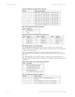
F49: Input states (16-bit bitmask)
F50: Output relay states (16-bit bitmask)
F51: DSP diagnostic flags (16-bit bitmask)
Bitmask
Input state
–––– –––– –––– –––x
Input 1 (0 = open, 1 = closed)
–––– –––– –––– ––x–
Input 2 (0 = open, 1 = closed)
–––– –––– –––– –x––
Input 3 (0 = open, 1 = closed)
–––– –––– –––– x–––
Input 4 (0 = open, 1 = closed)
–––– –––– –––x ––––
Input 5 (0 = open, 1 = closed)
–––– –––– ––x– ––––
Input 6 (0 = open, 1 = closed)
–––– –––– –x–– ––––
Input 7 (0 = open, 1 = closed)
–––– –––– x––– ––––
Input 8 (0 = open, 1 = closed)
–––– –––x –––– ––––
Input 9 (0 = open, 1 = closed)
–––– ––x– –––– ––––
Input 10 (0 = open, 1 = closed)
–––– –x–– –––– ––––
Input 11 (0 = open, 1 = closed)
–––– x––– –––– ––––
Input 12 (0 = open, 1 = closed)
–––x –––– –––– ––––
Input 13 (0 = open, 1 = closed)
––x– –––– –––– ––––
Input 14 (0 = open, 1 = closed)
–x–– –––– –––– ––––
Input 15 (0 = open, 1 = closed)
x––– –––– –––– ––––
Input 16 (0 = open, 1 = closed)
Bitmask
Output state
–––– –––– –––– –––x
Output relay 1 (0 = de-energized, 1 = energized)
–––– –––– –––– ––x–
Output relay 2 (0 = de-energized, 1 = energized)
–––– –––– –––– –x––
Output relay 3 (0 = de-energized, 1 = energized)
–––– –––– –––– x–––
Output relay 4 (0 = de-energized, 1 = energized)
–––– –––– –––x ––––
Output relay 5 (0 = de-energized, 1 = energized)
–––– –––– ––x– ––––
Output relay 6 (0 = de-energized, 1 = energized)
–––– –––– –x–– ––––
Output relay 7 (0 = de-energized, 1 = energized)
–––– –––– x––– ––––
Output relay 8 (0 = de-energized, 1 = energized)
–––– –––x –––– ––––
Self-test relay (0 = de-energized, 1 = energized)
Bitmask
Diagnostic flag
–––– –––– –––– –––x
A/D virtual ground (0 = OK, 1 = out of tolerance)
–––– –––– –––– ––x–
A/D subsystem (0 = OK, 1 = not responding)


