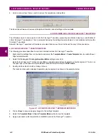
4-2
C60 Breaker Protection System
GE Multilin
4.1 ENERVISTA UR SETUP INTERFACE
4 HUMAN INTERFACES
4
RS485 COM2 Baud Rate
RS485 COM2 Parity
COM2 Minimum Response Time
COM2 Selection
RRTD Slave Address
RRTD Baud Rate
IP Address
IP Subnet Mask
Gateway IP Address
Ethernet Sub Module Serial Number
Network Address NSAP
IEC61850 Config GOOSE ConfRev
c) CREATING AND EDITING FLEXLOGIC™
You can create or edit a FlexLogic™ equation in order to customize the relay. You can subsequently view the automatically
generated logic diagram.
d) VIEWING ACTUAL VALUES
You can view real-time relay data such as input/output status and measured parameters.
e) VIEWING TRIGGERED EVENTS
While the interface is in either on-line or off-line mode, you can view and analyze data generated by triggered specified
parameters, via one of the following:
•
Event Recorder facility:
The event recorder captures contextual data associated with the last 1024 events, listed in
chronological order from most recent to oldest.
•
Oscillography facility:
The oscillography waveform traces and digital states are used to provide a visual display of
power system and relay operation data captured during specific triggered events.
f) FILE SUPPORT
•
Execution:
Any EnerVista UR Setup file which is double clicked or opened will launch the application, or provide focus
to the already opened application. If the file was a settings file (has a
URS
extension) which had been removed from
the Settings List tree menu, it will be added back to the Settings List tree menu.
•
Drag and Drop:
The Site List and Settings List control bar windows are each mutually a drag source and a drop target
for device-order-code-compatible files or individual menu items. Also, the Settings List control bar window and any
Windows Explorer directory folder are each mutually a file drag source and drop target.
New files which are dropped into the Settings List window are added to the tree which is automatically sorted alphabet-
ically with respect to settings file names. Files or individual menu items which are dropped in the selected device menu
in the Site List window will automatically be sent to the on-line communicating device.
g) FIRMWARE UPGRADES
The firmware of a C60 device can be upgraded, locally or remotely, via the EnerVista UR Setup software. The correspond-
ing instructions are provided by the EnerVista UR Setup Help file under the topic “Upgrading Firmware”.
Modbus addresses assigned to firmware modules, features, settings, and corresponding data items (i.e. default
values, minimum/maximum values, data type, and item size) may change slightly from version to version of firm-
ware. The addresses are rearranged when new features are added or existing features are enhanced or modified.
The
EEPROM DATA ERROR
message displayed after upgrading/downgrading the firmware is a resettable, self-test
message intended to inform users that the Modbus addresses have changed with the upgraded firmware. This
message does not signal any problems when appearing after firmware upgrades.
NOTE
Summary of Contents for C60
Page 2: ......
Page 4: ......
Page 11: ...GE Multilin C60 Breaker Protection System xi TABLE OF CONTENTS INDEX ...
Page 12: ...xii C60 Breaker Protection System GE Multilin TABLE OF CONTENTS ...
Page 32: ...1 20 C60 Breaker Protection System GE Multilin 1 5 USING THE RELAY 1 GETTING STARTED 1 ...
Page 50: ...2 18 C60 Breaker Protection System GE Multilin 2 2 SPECIFICATIONS 2 PRODUCT DESCRIPTION 2 ...
Page 128: ...4 30 C60 Breaker Protection System GE Multilin 4 3 FACEPLATE INTERFACE 4 HUMAN INTERFACES 4 ...
Page 394: ...9 4 C60 Breaker Protection System GE Multilin 9 1 FAULT LOCATOR 9 THEORY OF OPERATION 9 ...
Page 516: ...D 10 C60 Breaker Protection System GE Multilin D 1 OVERVIEW APPENDIXD D ...
Page 528: ...E 12 C60 Breaker Protection System GE Multilin E 2 DNP POINT LISTS APPENDIXE E ...


