9. ACCEPTANCE TESTS
GEK-106243E
DTP Digital Transformer Protection
9-1
9. ACCEPTANCE TESTS
In this section, the necessary tests to check proper operation of the relay are described. The relay must have the
factory configuration, so that the configurable inputs and outputs coincide with those indicated in the following
tests.
9.1 CONNECTIONS
Connect the relay as shown in the external connections diagram (figure 1).
The power supply must be connected to Q11 (Positive) and P11 (Negative).
Due to safety reasons, the external protection ground terminal should be securely grounded.
9.2 VISUAL INSPECTION
Check that the relay has not suffered any kind of damage due to transportation and handling.
Check that all screws are sufficiently tight and that the terminal strips have not been damaged in any way.
Check that the information on the nameplate coincides with that of the ordered model.
9.3 INSULATION TESTS
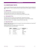
Progressively apply 2000 rms volts across all the terminals of a group short-circuited between them and ground
(or the case), during one second.
Progressively apply 2000 rms volts between groups, during one second.
The independent insulation groups are as follows:
GROUP
TERMINALS
DEFINITION
G1
A1..6, B1..6, E1..6, F1..6
Currents
G2
P5..9,
Q5..9
Trips
G3
P11, Q11
Power Supply
G4
J1.. 4, K1..4
Inputs
G5
J5..12,
K5..12 Outputs
Summary of Contents for DTP-B
Page 23: ...3 OPERATING PRINCIPLES 3 6 DTP B Digital Transformer Protection GEK 106243E ...
Page 53: ...10 INSTALLATION AND MAINTENANCE 10 2 DTP B Digital Transformer Protection GEK 106243E ...
Page 68: ...12 FIGURES GEK 106243E DTP Digital Transformer Protection 12 3 Figure 3 RS 232 Connection ...
Page 69: ...12 FIGURES 12 4 DTP B Digital Transformer Protection GEK 106243E Figure 4 Dimensions Diagram ...
Page 70: ...12 FIGURES GEK 106243E DTP Digital Transformer Protection 12 5 Figure 5 Front View ...


