GE Multilin
F35 Multiple Feeder Protection System
4-17
4 HUMAN INTERFACES
4.3 FACEPLATE INTERFACE
4
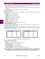
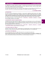
The relay is shipped with the default label for the LED panel 2. The LEDs, however, are not pre-programmed. To match the
pre-printed label, the LED settings must be entered as shown in the
User-programmable LEDs
section of chapter 5. The
LEDs are fully user-programmable. The default labels can be replaced by user-printed labels for both panels as explained
in the following section.
Figure 4–21: LED PANEL 2 (DEFAULT LABELS)
4.3.3 CUSTOM LABELING OF LEDS
a) ENHANCED FACEPLATE
The following procedure requires the pre-requisites listed below.
•
EnerVista UR Setup software is installed and operational.
•
The F35 settings have been saved to a settings file.
•
The F35 front panel label cutout sheet (GE Multilin part number 1006-0047) has been downloaded from
www.GEindustrial.com/multilin/support/ur
and printed.
•
Small-bladed knife.
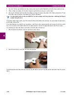
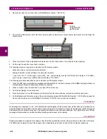
This procedure describes how to create custom LED labels for the enhanced front panel display.
1.
Start the EnerVista UR Setup software.
2.
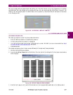
Select the
Front Panel Report
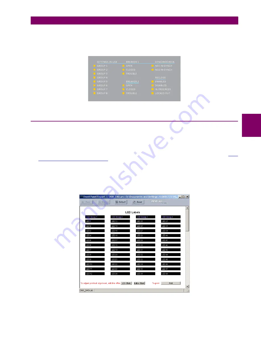
item at the bottom of the menu tree for the settings file. The front panel report window
will be displayed.
Figure 4–22: FRONT PANEL REPORT WINDOW
3.
Enter the text to appear next to each LED and above each user-programmable pushbuttons in the fields provided.
842784A1.CDR
Summary of Contents for F35
Page 2: ......
Page 4: ......
Page 296: ...5 174 F35 Multiple Feeder Protection System GE Multilin 5 9 TESTING 5 SETTINGS 5 ...
Page 328: ...7 8 F35 Multiple Feeder Protection System GE Multilin 7 2 TARGETS 7 COMMANDS AND TARGETS 7 ...
Page 350: ...A 16 F35 Multiple Feeder Protection System GE Multilin A 1 PARAMETER LIST APPENDIXA A ...
Page 422: ...B 72 F35 Multiple Feeder Protection System GE Multilin B 4 MEMORY MAPPING APPENDIXB B ...
Page 472: ...E 12 F35 Multiple Feeder Protection System GE Multilin E 2 DNP POINT LISTS APPENDIXE E ...


