Installation
2-1
October 2007
Introduction
This chapter explains the installation of the benchtop and wall-mount
versions of the
OptiSonde
, the various sensors used with the system,
and the I/O and power wiring.
Benchtop Installation
Mounting the Benchtop
The
OptiSonde
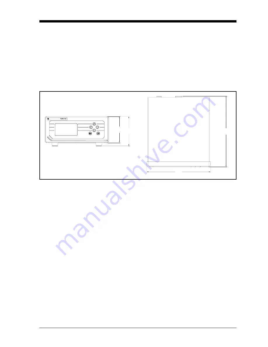
benchtop dimensions are shown in Figure 2-1 below.
A metal stand on the bottom of the case can be unfolded to elevate the
front of the instrument for easier viewing, if desired.
Figure 2-1:
OptiSonde
Benchtop Dimensions
Wiring the Benchtop
Input Power
The
OptiSonde
operates with input power from 100 to 240 VAC
±10%. (See Figure 2-2 below.) The OptiSonde’s voltage and
frequency rating are listed on the product label. A DC option offers a
minimum of 18 to a maximum of 32 VDC operation (See Figure 2-3
on the next page.)
3.70
[94]
3.30
[84]
Note: units are inches [mm]
8.00
[203]
8.84
[225]
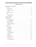
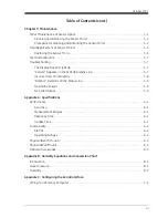
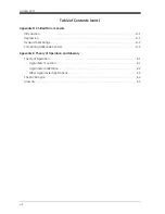
Summary of Contents for 1111H
Page 1: ...GE Sensing OptiSonde General Eastern Chilled Mirror Hygrometer User s Manual ...
Page 9: ...Chapter 1 ...
Page 15: ...Chapter 2 ...
Page 33: ...Chapter 3 ...
Page 43: ...Chapter 4 ...
Page 57: ...Chapter 5 ...
Page 68: ...Appendix A ...
Page 73: ...Appendix B ...
Page 74: ...Humidity Equations and Conversion Chart Introduction B 1 Vapor Pressure B 1 Humidity B 2 ...
Page 78: ...Appendix C ...
Page 79: ...Configuring the Serial Interface Wiring to a Personal Computer C 1 ...
Page 82: ...Appendix D ...
Page 87: ...Appendix E ...
Page 88: ...Theory of Operation and Glossary Theory of Operation E 1 The PACER Cycle E 4 Glossary E 5 ...


