Installation
2-5
October 2007
Wiring the Wall-Mount
(cont.)
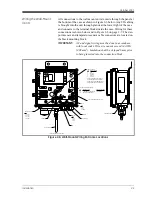
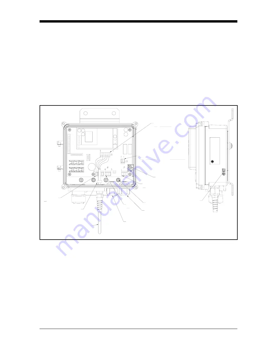
All connections to the wall-mount unit are made through the panel at
the bottom of the case as shown in Figure 2-6 below. Any I/O cabling
is brought into the unit through glands at the lower right of the case
and connects to the terminal blocks inside the case. Wiring for these
connections is shown below and in Figure 2-8 on page 2-7. The dew
point sensor and temperature sensor cable connectors are located on
the black mounting block.
IMPORTANT:
AC and signal wiring must be done in accordance
with local codes. Wire size cannot exceed 14 AWG
(2.08 mm
2
). Insulation shall be stripped 6 mm prior
to being inserted into the connection block.
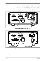
Figure 2-6: Wall-Mount Wiring Entrance Locations
CHASSIS GROUND
ANALOG INPUTS
PIN
1. OUTA +
2. OUTA -
3. OUTB +
4. OUTB -
FERRITE
LOCAL SHOWN
COVER ASSEMBLY NOT SHOWN
RS232
PIN
1. TX
2. RX
3. RTN
I/O
RELAY
PIN
1. NO
2. NC
3. COMM
A/C POWER
SHIELD
EARTH GROUND CONNECTION
A/C POWER TERMINAL BLOCK
1. L LINE POWER CONNECTION 100-240VAC
2. N NEUTRAL CONNECTION
PIN DESCRIPTION SUPPLY VOLTAGE
TEMP. SENSOR
PIN
1. RED
2. WHITE
3. GREEN
4. BLACK
5. SHIELD
WIRE COLORS
NOTE: CUSTOMER MUST INSTALL
SUPPLIED FERRITE (P/N 222-028)
OVER THE END OF TEMPERATURE
SENSOR ON LOCAL AND REMOTE.
Summary of Contents for 1111H
Page 1: ...GE Sensing OptiSonde General Eastern Chilled Mirror Hygrometer User s Manual ...
Page 9: ...Chapter 1 ...
Page 15: ...Chapter 2 ...
Page 33: ...Chapter 3 ...
Page 43: ...Chapter 4 ...
Page 57: ...Chapter 5 ...
Page 68: ...Appendix A ...
Page 73: ...Appendix B ...
Page 74: ...Humidity Equations and Conversion Chart Introduction B 1 Vapor Pressure B 1 Humidity B 2 ...
Page 78: ...Appendix C ...
Page 79: ...Configuring the Serial Interface Wiring to a Personal Computer C 1 ...
Page 82: ...Appendix D ...
Page 87: ...Appendix E ...
Page 88: ...Theory of Operation and Glossary Theory of Operation E 1 The PACER Cycle E 4 Glossary E 5 ...

